
Automatic grinding and polishing machine for engine crankshafts

An engine and polishing machine technology, applied in grinding/polishing equipment, surface polishing machine tools, automatic grinding control devices, etc., can solve the problem that the consistency of multiple parts is very different, limit the service life of the engine, and affect the entire engine. performance and other issues, to achieve the effect of shortening processing time, reducing force, and improving consistency

Active Publication Date: 2013-09-25
山西东鑫衡隆机械制造股份有限公司
View PDF9 Cites 10 Cited by
  • Summary
  • Abstract
  • Description
  • Claims
  • Application Information

AI Technical Summary

Problems solved by technology

The traditional processing method adopts manual polishing, which is usually carried out manually with a simple polishing machine. Polishing the crankshaft main shaft and connecting rod parts one by one is not only inefficient, time-consuming and laborious, but also the shape and position tolerance of a single part cannot be guaranteed. Consistency is very different, which has been a bottleneck problem that has restricted the quality of crankshaft processing for a long time, directly affects the overall performance of the engine, and limits the service life of the engine

Method used


Image

  • Automatic grinding and polishing machine for engine crankshafts
  • Automatic grinding and polishing machine for engine crankshafts
  • Automatic grinding and polishing machine for engine crankshafts

Examples


Embodiment Construction

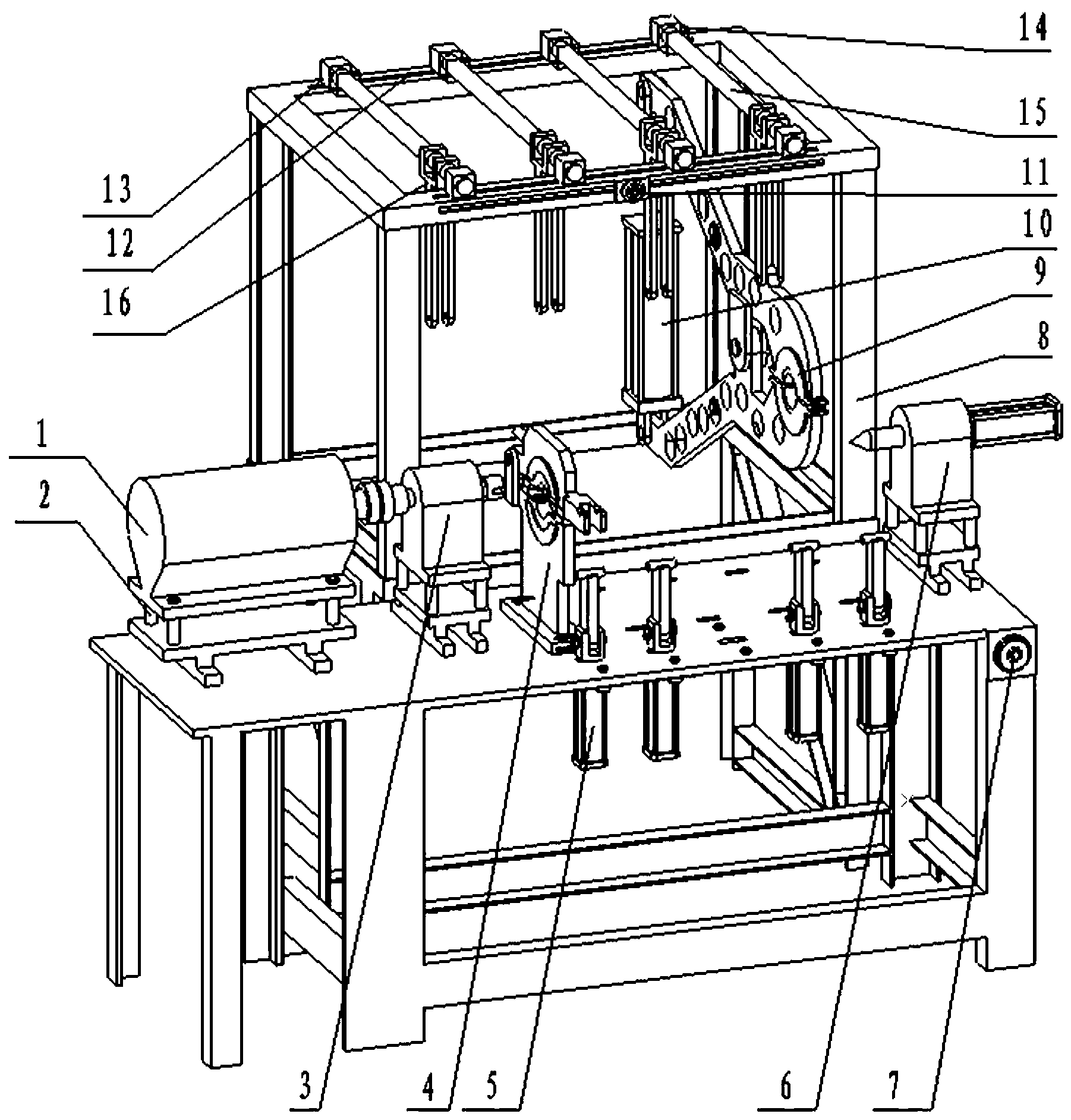
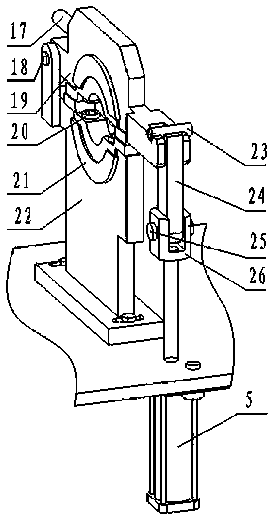
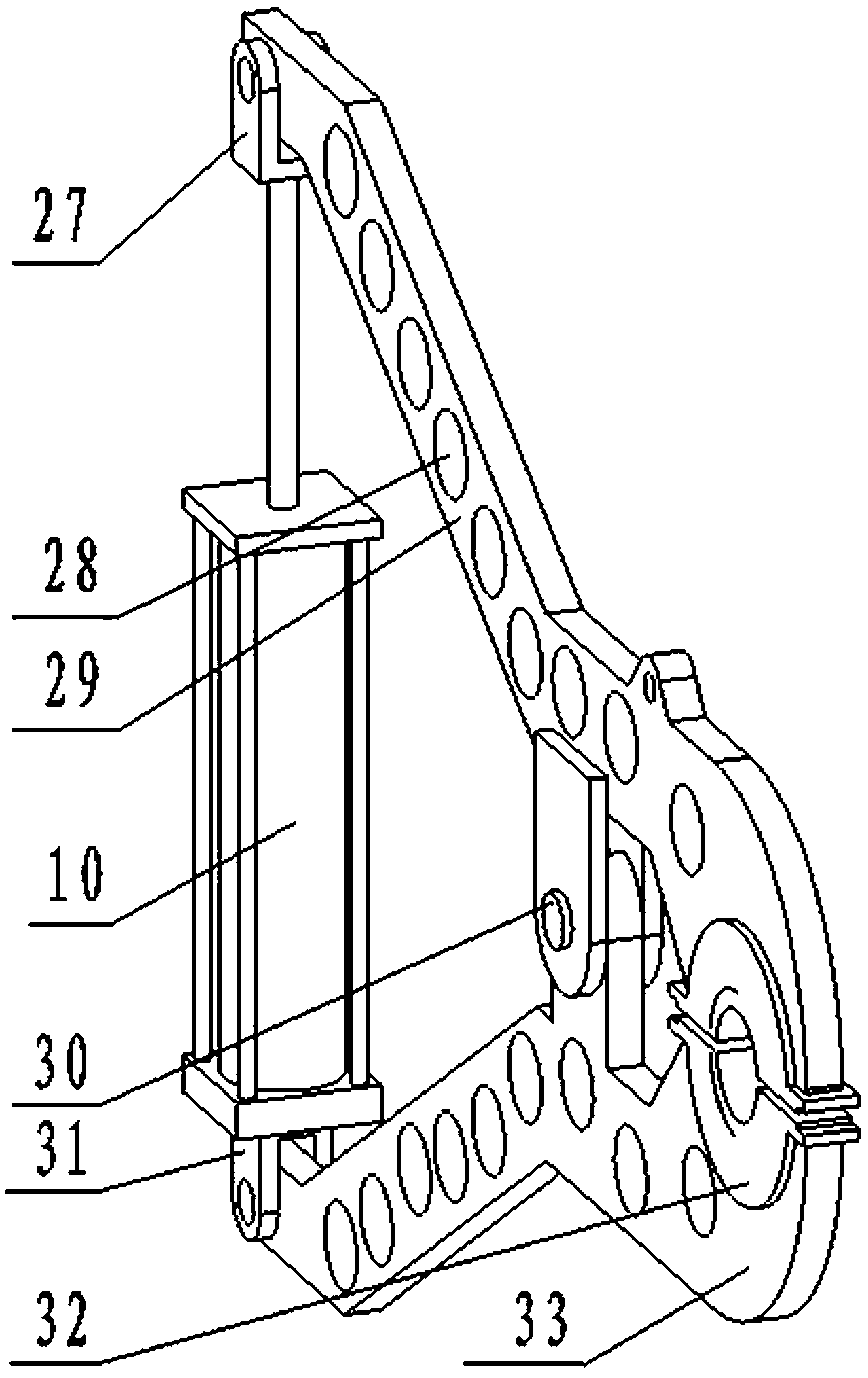
[0025] An engine crankshaft automatic grinding and polishing machine, such as figure 1 Shown, comprise front body 2 and rear body 8. The left end of the front body 2 is equipped with a motor 1 and a transmission adjustment device 3 in sequence, the output shaft of the motor 1 is connected with the transmission adjustment device 3, the right end of the front body 2 is equipped with a tail positioning device 6, and the transmission adjustment device 3 and the tail positioning device The crankshaft spindle polishing device 4 and the first cylinder 5 are installed between the 6, the first cylinder 5 is arranged on the crankshaft spindle polishing device 4, the crankshaft spindle clamping controller 7 is installed on the front body 2, and the crankshaft spindle clamping controller 7 Connect with the first cylinder 5. The rear body 8 is provided with a crankshaft connecting rod polishing device 9 and a crankshaft connecting rod clamping controller 11, the crankshaft connecting rod ...


PUM


Abstract

The invention relates to an automatic grinding and polishing machine for engine crankshafts. The automatic grinding and polishing machine comprises a front body and a rear body. A motor and a transmission adjusting device are sequentially disposed at the left end of the front body. An output shaft of the motor is connected with the transmission adjusting device. A tail positioning device is disposed at the right end of the front body. A crankshaft spindle polishing device is disposed between the transmission adjusting device and the tail positioning device. A first air cylinder is disposed on the crankshaft spindle polishing device. A crankshaft spindle clamp controller which is connected with the first air cylinder is further disposed on the front body. A crankshaft connecting rod polishing device and a crankshaft connecting rod clamp controller which are connected are disposed on the rear body. A second air cylinder is disposed on the crankshaft connecting rod polishing device. By the automatic grinding and polishing machine which is simple to operate and high in work efficiency, crankshaft spindles and crankshaft connecting rods can be polished simultaneously, quality requirements of crankshaft polishing can be guaranteed, and consistency of the spindles and the connecting rods can be increased.

Description

[0001] technical field [0002] The invention belongs to machining equipment, in particular to an automatic grinding and polishing machine for engine crankshafts. Background technique [0003] The engine crankshaft is the most important part of the engine after the cylinder block. Its processing quality directly affects the overall performance of the engine, and the surface treatment and polishing is the final process of the processing process, which is the decisive factor for the quality. The traditional processing method adopts manual polishing, which is usually carried out manually with a simple polishing machine. Polishing the crankshaft main shaft and connecting rod parts one by one is not only inefficient, time-consuming and laborious, but also the shape and position tolerance of a single part cannot be guaranteed. Consistency is even more different, which has been a bottleneck problem that has restricted the quality of crankshaft processing for a long time, directly a...

Claims


Application Information

Patent Timeline
Patent Type & Authority Applications(China)
IPC IPC(8): B24B5/42B24B41/06B24B29/02B24B51/00
Inventor 褚京生常显峰张强强
Owner 山西东鑫衡隆机械制造股份有限公司
Learn More