
Spherical swing device for large rotary forging press

A technology of swing device and rotary rolling machine, which is applied in the direction of transmission device, friction transmission device, forging/pressing/hammer device, etc., which can solve the problems of strain, damage, and restriction of large-scale rotary rolling machine research and development, and achieve friction The effect of reducing and ensuring reliability

Active Publication Date: 2013-09-25
CHENGDU XINZHU ROAD & BRIDGE MASCH CO LTD
View PDF9 Cites 3 Cited by
  • Summary
  • Abstract
  • Description
  • Claims
  • Application Information

AI Technical Summary

Problems solved by technology

In the structure of the existing swing rolling machine, the oscillating device adopts the power transmission structure of the motor and the driving gearbox. The ball head of the main shaft is made of steel, and the ball bowl is made of copper-based alloy. The coefficient of friction is 0.1-0.15, and the copper alloy is expensive. If the contact area between the ball head and the bowl does not reach more than 70%, it is easy to accelerate wear and damage, and the maintenance cost is high.
Even the strain caused by excessive contact stress makes the rotary rolling machine unable to work stably and reliably for a long time, thus limiting the research and development of large rotary rolling machines with a pressure level above 800 tons

Method used


Image

  • Spherical swing device for large rotary forging press
  • Spherical swing device for large rotary forging press

Examples


Embodiment Construction

[0015] The present invention will be further described below in combination with specific embodiments and accompanying drawings.

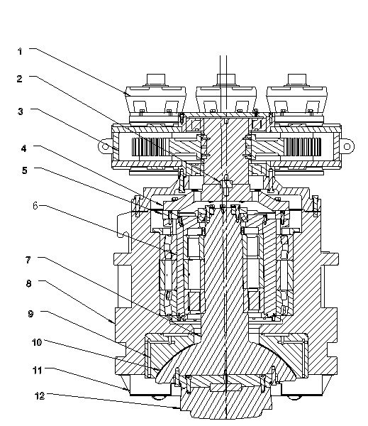
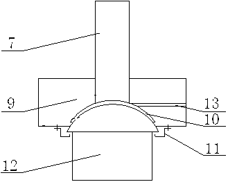
[0016] Example: such as figure 1 , 2 As shown, a spherical oscillating device for a large-scale rotary rolling machine includes a fixed seat 8 and a drive gearbox 3 and an oil motor 1 fixed on the top thereof. The drive gearbox 3 drives the long key 2 and the connecting plate 4 It is fixedly connected with the deflection sleeve shaft system 6 in the fixed seat 8. The center of the deflection sleeve shaft system 6 is the swing main shaft 7, and the lower end of the swing main shaft 7 is a ball head and a swing head 12, and passes through the ball head and the ball bowl 9. Cooperate to realize the rotation connection, the surface of the ball bowl 9 is provided with a layer of polymer wear-resistant layer 10, and an oil inlet hole 13 is also provided on the ball bowl 9 to pass directly from the outside to the contact surface of the ball head and the ...


PUM


Abstract

The invention discloses a spherical swing device for a large rotary forging press. The spherical swing device comprises a fixing seat, driving gear boxes and an oil motor. The driving gear boxes are fixed at the top of the fixing seat, and are fixedly connected with an angle-deflected sleeve spindle set inside the fixing seat through a long driving bond and a connecting tray, a swing spindle is located at the center of the angle-deflected sleeve spindle set, a ball head and a swing head are arranged at the lower end of the swing spindle, and rotational connection is achieved through cooperation of the ball head and a ball bowl. A high molecular wear-resistant layer is arranged on the surface of the ball bowl, one oil supply hole extending from the outside to a contact surface of the ball head and the ball bowl is formed the ball bowl, and an oil receiver with an annular groove is fixed at the bottom of the ball wall along a contact circle of the ball bowl head through bolts. The spherical swing device for the large rotary forging press has the advantages that the angle-deflected sleeve spindle set has a function of floating compensation, so that clearance self-compensation after spherical pairs are slightly worn can be achieved; the oil supply hole formed in a ball bowl body serves as a forced lubrication cooling oil channel, so that friction is greatly reduced, and reliability of operation of a large-tonnage rotary forging press is guaranteed.

Description

technical field [0001] The invention relates to the technical field of forging equipment, in particular to a spherical oscillating device for a large oscillating forging machine with a pressure level above 800 tons. Background technique [0002] The rotary forging machine is a precision forging forming equipment that replaces the overall forming with partial forming in the metal forging forming process. Its forming force is only one-twentieth to one-fifth of the forming force of the general forging equipment for the same workpiece. [0003] The spherical oscillating device is a working mechanism to achieve yaw forming, and the oscillating main shaft ball head and ball bowl of this mechanism are the main components that bear and transmit the oscillating force. In the structure of the existing swing rolling machine, the oscillating device adopts the power transmission structure of the motor and the driving gearbox. The ball head of the main shaft is made of steel, and the ball...

Claims


Application Information

Patent Timeline
IPC IPC(8): B21J13/00F16H19/08
Inventor 冯克敏张有明李世宽杨凯理杨强赖华
Owner CHENGDU XINZHU ROAD & BRIDGE MASCH CO LTD
Learn More