Electric connector and terminals thereof

An electrical connector and terminal technology is applied in the field of electrical connectors and their terminals that are more convenient for tools to push and install on an insulating body. Achieve the effect of avoiding excessive stress concentration and convenient pressure area

Inactive Publication Date: 2013-09-18
MOLEX INTERCONNECT SHANGHAI +1
View PDF6 Cites 8 Cited by
  • Summary
  • Abstract
  • Description
  • Claims
  • Application Information

AI Technical Summary

Problems solved by technology

[0003] However, when the existing terminals are assembled, only a strip connecting portion 12 on the top surface of the base 11 is used for pushing by tools. Because the volume of terminal manufacturing is gradually reduced, the strip connecting portion 12 is often pushed by tools. If the area is too small, there is a problem that the tool is not easy to push against the connecting part 12 of the strip; in addition, when the existing terminal is installed on the insulating body, only the lower half of the base 11 is fixed on the insulating body. It often causes the upper part of the base 11 to deform due to stress when the terminal is crimped with the upper circuit board, so that the base 11 is inclined relative to the insulating body and cannot be firmly fixed to the insulating body

Method used


Image

  • Electric connector and terminals thereof
  • Electric connector and terminals thereof
  • Electric connector and terminals thereof

Examples


Embodiment Construction

[0024] The aforementioned and other technical contents, features and effects of the present invention will be clearly presented in the following detailed description of two preferred embodiments with reference to the accompanying drawings.

[0025] Before the present invention is described in detail, it should be noted that in the following description, similar components are denoted by the same numerals.

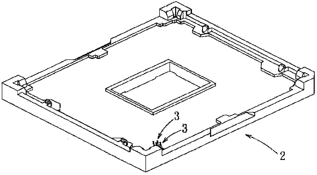
[0026] refer to figure 2 , the first preferred embodiment of the electrical connector of the present invention is a planar grid array electrical connector, suitable for electrically connecting a chip module (not shown), the first preferred embodiment includes an insulating body 2 and multiple A conductive terminal 3.

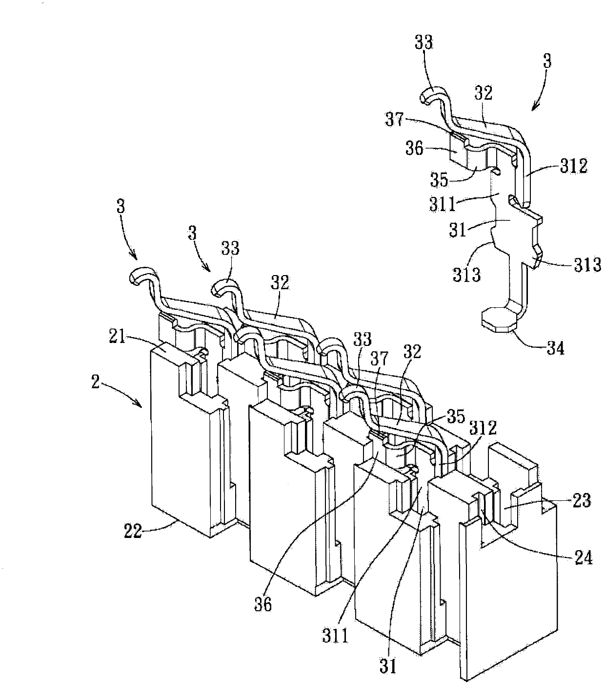
[0027] In order to make the accompanying drawings clearly show the features of the first preferred embodiment, Figure 3 to Figure 5 Only a partial area of ​​the electrical connector is shown for enlarged display. refer to Figure 3 to Figure 5 , the ins...


PUM


Abstract

The invention provides an electric connector. The electric connector comprises an insulation body which comprises a number of terminal grooves and a number of limiting grooves, and a number of terminals which are respectively and correspondingly accommodated in a number of terminal grooves. Each terminal comprises a body which is located in the corresponding terminal groove and is fixedly arranged on the insulation body, an elastic arm which extends upward from the body, a first contact part which is formed on the tail end of the elastic arm, a second contact part which extends downward from the body, a curved arm which laterally bends and extends from the body, and a limiting part which is formed on the tail end of the curved arm and is partially accommodated in a limiting groove. Through the top surface of each curved arm, a number of terminals have large areas and can be pushed and pressed by a tool. Each limiting part is accommodated in each limiting groove, which can increase the auxiliary supporting of the terminals on the insulation body, so that the terminals can be easily pushed and pressed by the tool and are stable on the insulation body.

Description

technical field [0001] The invention relates to an electrical connector and its terminals, in particular to an electrical connector and its terminals which are more convenient for tools to push and be installed on an insulating body Background technique [0002] The electrical connector generally includes an insulating body and a plurality of conductive terminals disposed on the insulating body. As the development of modern electronic equipment gradually tends to be miniaturized, the volume of electrical connectors is also developing towards miniaturization, and the size of its terminals is naturally reduced accordingly. Due to the miniaturization of the terminal, the elasticity of the terminal is often difficult to withstand the pressure exerted by the circuit board on the terminal. At present, the industry has developed a corresponding solution to this problem. Refer to figure 1 , which is a kind of electrical connector terminal disclosed in Taiwan Patent Publication No. ...

Claims


Application Information

Patent Timeline
Patent Type & Authority Applications(China)
IPC IPC(8): H01R13/02H01R13/20H01R13/40H01R12/55H01R33/74
Inventor 郑有祥卡赫利克·杰里
Owner MOLEX INTERCONNECT SHANGHAI
Why Eureka
Try Eureka