
Image compensation and correction method and banknote detection and identification device

An image compensation and original image technology is applied in the field of banknote identification and verification, which can solve the problems of affecting the working efficiency of the identification banknote inspection device, and the compensation and correction time affecting the performance of the MCU system, so as to save the compensation and correction process, improve the work efficiency, and improve the system. performance effect

Active Publication Date: 2013-09-18
GRG BAKING EQUIP CO LTD
View PDF17 Cites 25 Cited by
  • Summary
  • Abstract
  • Description
  • Claims
  • Application Information

AI Technical Summary

Problems solved by technology

Because MCU also takes into account the main tasks such as banknote recognition algorithm and information communication, in the process of MCU information processing, too much compensation and correction time for CIS will affect the system performance of MCU, and then affect the working efficiency of the identification and verification device

Method used


Image

  • Image compensation and correction method and banknote detection and identification device
  • Image compensation and correction method and banknote detection and identification device
  • Image compensation and correction method and banknote detection and identification device

Examples


Embodiment Construction

[0049] The following will clearly and completely describe the technical solutions in the embodiments of the present invention with reference to the accompanying drawings in the embodiments of the present invention. Obviously, the described embodiments are only some, not all, embodiments of the present invention. Based on the embodiments of the present invention, all other embodiments obtained by persons of ordinary skill in the art without creative efforts fall within the protection scope of the present invention.

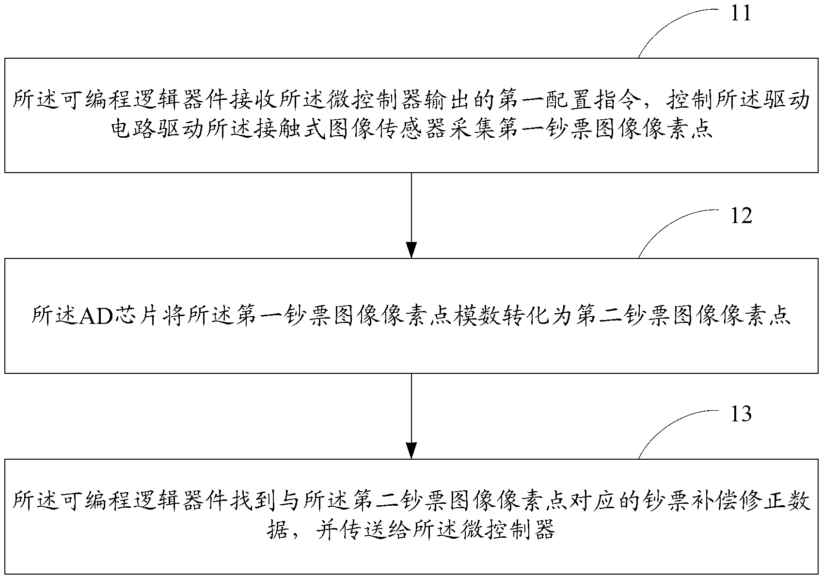
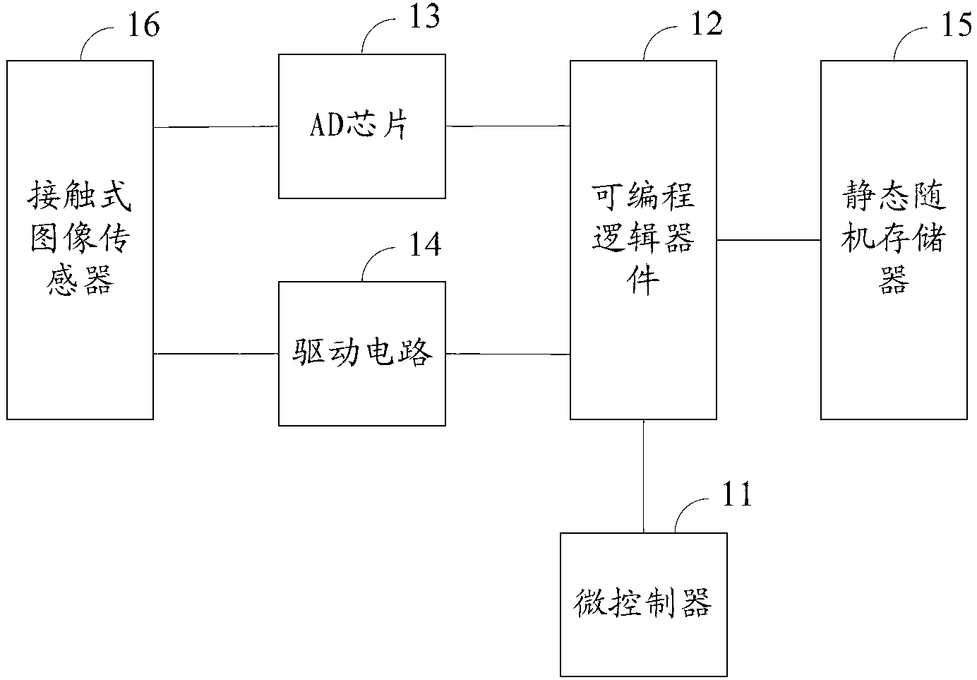
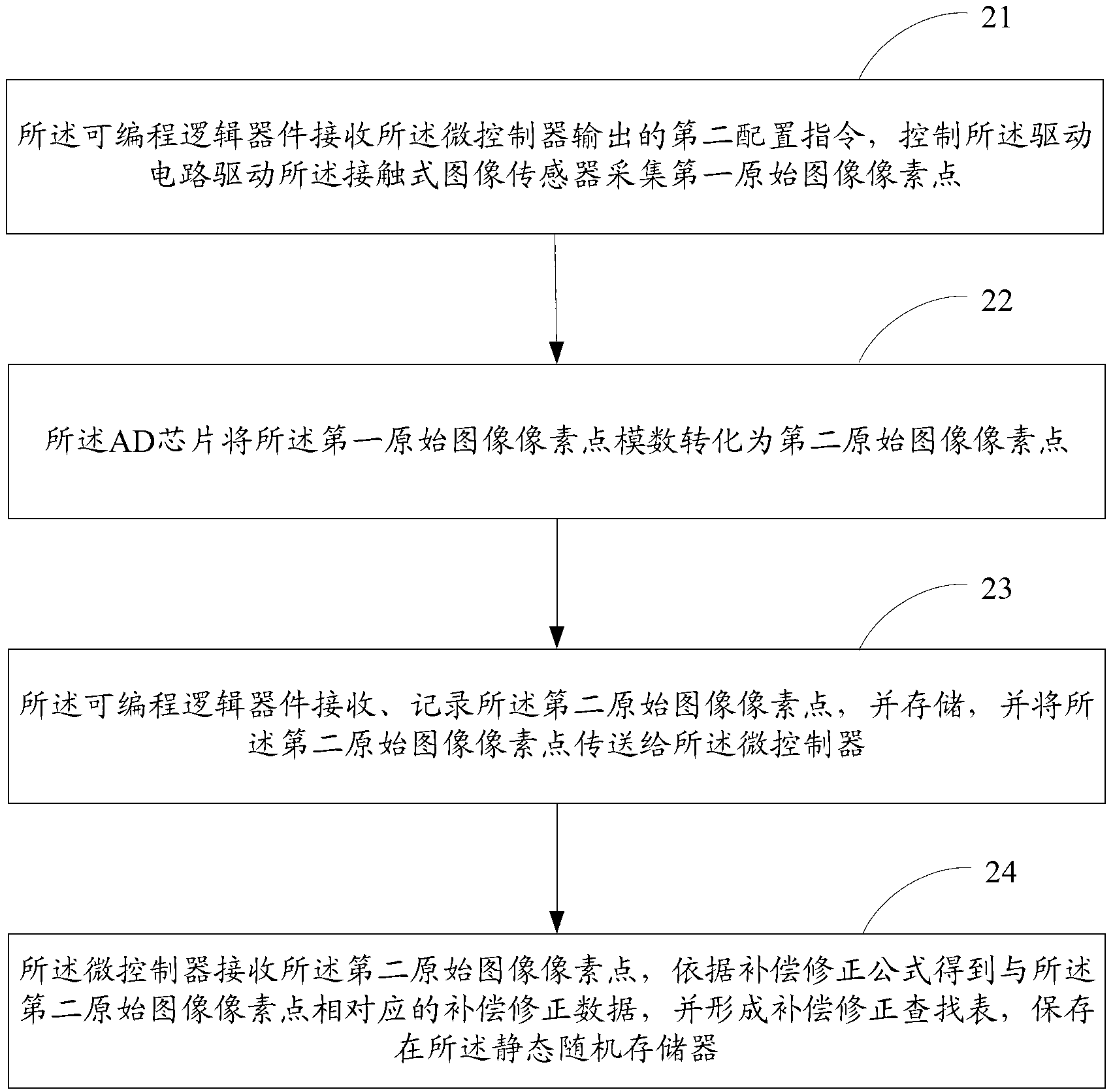
[0050] Such as figure 1 As shown, the embodiment of the present invention discloses a flow chart of an image compensation and correction method. The compensation and correction method is applied to the identification and verification device. The structural schematic diagram of the identification and verification device is as follows figure 2 As shown, it includes: a microcontroller 11, a programmable logic device 12 (Field-Programmable Gate Array, FPGA) connected ...


PUM


Abstract

The invention provides an image compensation and correction method and a banknote detection and identification device. The image compensation and correction method is applied to the banknote detection and identification device. The banknote detection and identification device comprises a micro control unit, a field programmable gate array, an AD (Analog to Digital) chip, a driving circuit, a static random access memory and a contact image sensor, wherein the field programmable gate array is connected with the micro control unit, the AD chip, the driving circuit and the static random access memory are connected with the field programmable gate array respectively, and the contact image sensor is connected with the AD chip and the driving circuit respectively. A compensation and correction lookup table is pre-stored in the static random access memory and the field programmable gate array accesses the static random access memory to obtain banknote compensation and correction data corresponding to banknote image pixels and transmit to the micro control unit, so that the micro control unit directly obtains the banknote compensation and correction data from the field programmable gate array without performing compensation and correction on the obtained banknote image pixels any more, accordingly the system performance of the micro control unit is improved, and then the working efficiency of the banknote detection and identification device is improved.

Description

technical field [0001] The invention relates to the technical field of currency identification and verification, and more specifically, relates to an image compensation correction method and a currency identification and verification device. Background technique [0002] The contact image sensor (Contact Image Sensor, CIS) is the most common optical sensor in the identification and verification device, and is often used for face value recognition and authenticity identification of banknotes. The currently commonly used CIS is generally composed of multiple segments spliced ​​internally. Due to factors such as manufacturing and splicing processes, there are differences between the photosensitive units of each segment of the CIS, which makes the brightness of each segment of the original image directly collected by the CIS vary, which affects recognition. The banknote identification and authenticity identification of banknotes by the banknote detector requires compensation and...

Claims


Application Information

Patent Timeline
IPC IPC(8): G07D7/20
CPCG07D7/2008G07D7/202H04N25/772G06T7/0002
Inventor 黄国强刘梦涛
Owner GRG BAKING EQUIP CO LTD
Learn More