Abnormal waveform recording method for oscilloscope with high capture rate

An abnormal waveform and oscilloscope technology, which is applied in the field of abnormal waveform recording of high capture rate oscilloscopes, can solve the problems of inability to observe abnormal waveforms, inability to fully observe the whole picture of abnormal waveforms, and inability to locate the time point when abnormal waveforms appear, so as to reduce the observation work. Quantity, improved capture capability, and the effect of easy analysis

Inactive Publication Date: 2013-09-18
UNIV OF ELECTRONICS SCI & TECH OF CHINA
View PDF5 Cites 20 Cited by
  • Summary
  • Abstract
  • Description
  • Claims
  • Application Information

AI Technical Summary

Problems solved by technology

[0010] Although the existing anomaly detection and observation technology has improved the capture rate of abnormal waveforms to a certain extent, and can observe the normal waveforms before and after the occurrence of abnormal waveforms, there are still many deficiencies, such as: 1) It is impossible to completely observe each abnormal waveform 2) It is impossible to observe the abnormal waveform that appears in a long period of time; 3) It is impossible to locate the time point of each occurrence of the abnormal waveform

Method used


Image

  • Abnormal waveform recording method for oscilloscope with high capture rate
  • Abnormal waveform recording method for oscilloscope with high capture rate
  • Abnormal waveform recording method for oscilloscope with high capture rate

Examples


Embodiment

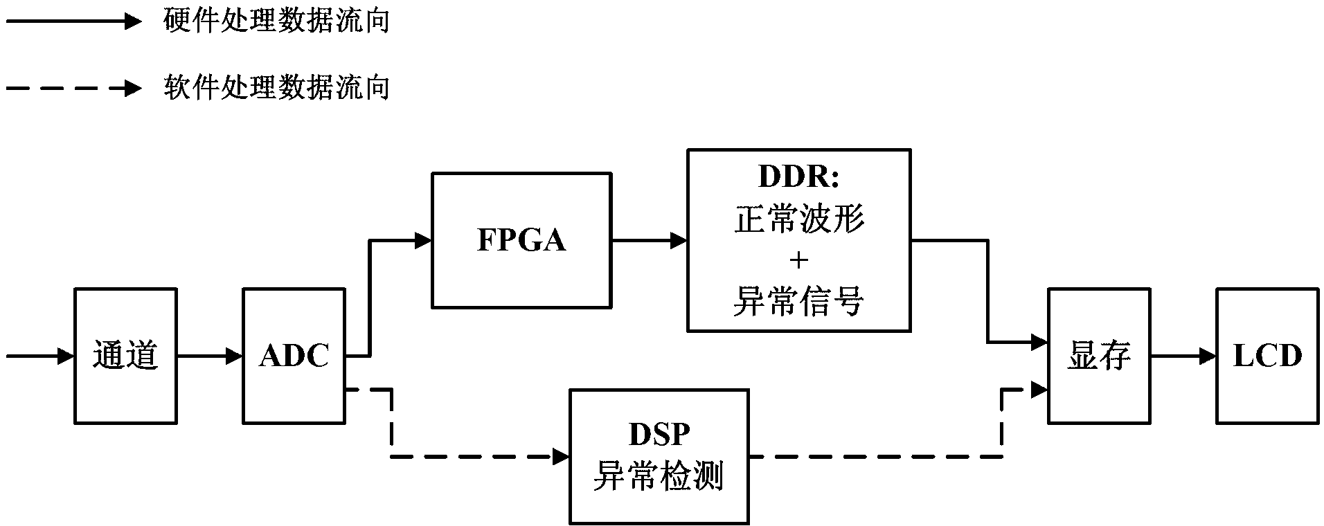
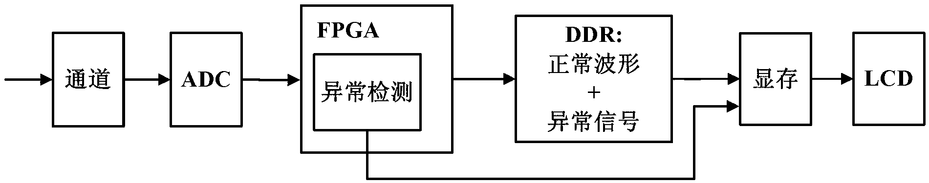
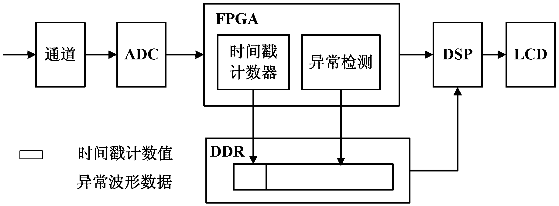
[0065] Taking an ADC with a vertical resolution of d=8bit to collect signals, and the number of sampling points for each collection is k=600 as an example, the specific implementation of the abnormal waveform recording and observation technology of the high capture rate oscilloscope of the present invention will be described.

[0066] (1) Establish a clock signal CLK with a period of T=1ms and a counter with n=32 bits in the FPGA. Then the accuracy of recording the real-time time of the abnormal waveform is 1ms, and the 32-bit register counts the clock cycle of period T=1ms, which can realize 2 32 / (3600*1000) = 1193 hour counts.

[0067] (2) In this embodiment, the online waveform is selected as an abnormality detection template; 1000 pieces of normal waveform data collected by the ADC are statistically analyzed to establish an abnormality detection template with 600 sampling points.

[0068] (3) Turn on the anomaly detection mode of the oscilloscope.

[0069] (4) The DSP r...


PUM


Abstract

The invention discloses an abnormal waveform recording method for an oscilloscope with a high capture rate. The method comprises the following steps: arranging a time stamp counter in an FPGA (Field Programmable Gate Array); binding a time stamp with a real-time clock at a DSP (Digital Signal Processor) end; comparing waveform data acquired by using the FPGA with an abnormal waveform detection template; when an abnormal waveform appears, storing abnormal waveform data and a corresponding time stamp in a DDR (Double Data Rate); and calculating the generation time of the abnormal waveform data via a corresponding relation between the time stamp and the real-time clock at the DSP end so as to realize time positioning of abnormal waveforms. According to the method, only abnormal waveform data are stored, and normal waveform data are not stored, so that the abnormal waveform capturing capacity can be increased; and meanwhile, time positioning of abnormal waveforms is also realized, and manual observation and recording are not required. Abnormal waveforms can be displayed by adopting multiple display modes, so that abnormal waveforms can be analyzed conveniently.

Description

technical field [0001] The invention belongs to the technical field of digital oscilloscopes, and more specifically relates to a method for recording abnormal waveforms of an oscilloscope with a high capture rate. Background technique [0002] In recent years, as modern electronic signals have become increasingly complex and diverse, the frequency range of signals has been continuously expanded, and the transient and non-stationary signals have been increasing, which has brought challenges to electronic design. As the most commonly used time-domain testing instrument, an oscilloscope needs to be able to effectively capture and observe abnormal waveforms in circuit design and system debugging, so as to analyze the time and cause of failures. [0003] The waveform capture rate of the oscilloscope is an important evaluation index of the oscilloscope. It refers to the number of waveforms (wfms / s) that the oscilloscope can capture and display per unit time. It expresses the amoun...

Claims


Application Information

Patent Timeline
Patent Type & Authority Applications(China)
IPC IPC(8): G01R13/02
Inventor 赵勇叶芃蒋俊邱渡裕曾浩
Owner UNIV OF ELECTRONICS SCI & TECH OF CHINA
Why Eureka
Try Eureka