Eureka AIR delivers breakthrough ideas for toughest innovation challenges, trusted by R&D personnel around the world.

An Equal Arm Length Heterodyne Laser Interferometric Ranging System

A technology of laser interference and ranging system, applied in measurement devices, optical devices, instruments, etc., can solve the problems of laser measurement error, lack of noise isolation system, unstable laser frequency, etc. Influence, the effect of reducing the effects of atmospheric disturbances

Inactive Publication Date: 2016-04-13
INST OF MECHANICS - CHINESE ACAD OF SCI
View PDF4 Cites 0 Cited by
  • Summary
  • Abstract
  • Description
  • Claims
  • Application Information

AI Technical Summary

Problems solved by technology

In addition, the frequency instability of the laser will also cause the measurement error of the heterodyne laser interferometer due to the inequality of the reference light and the measurement light: ΔL=L·δυ / υ, where L is the light of the reference light and the measurement light δυ is the frequency instability of the laser, and υ is the frequency of the laser; at the same time, the initial phase fluctuation of the laser, as well as various noise sources caused by optical platforms, components and optical fibers, etc. will also cause system measurement errors
[0005] The current laser interferometric ranging system generally does not have a noise isolation system. At the same time, the interference optical path is unequal, and there is no related noise-cancelling reference interferometer. At the same time, due to the lack of noise isolation measures such as vibration isolation, heat insulation and electromagnetic shielding, it is impossible to achieve long-term measurement

Method used


Image

  • An Equal Arm Length Heterodyne Laser Interferometric Ranging System
  • An Equal Arm Length Heterodyne Laser Interferometric Ranging System
  • An Equal Arm Length Heterodyne Laser Interferometric Ranging System

Examples


Embodiment Construction

[0074] Embodiments of the present invention will be described in detail below in conjunction with the accompanying drawings. It should be noted that, in the case of no conflict, the embodiments in the present application and the features in the embodiments can be combined arbitrarily with each other.

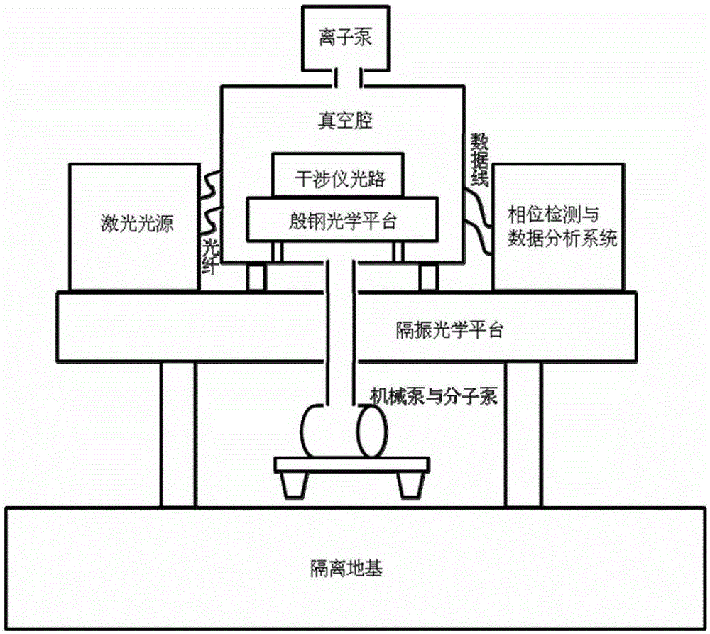
[0075] The present invention provides as attached figure 1 An equi-length heterodyne laser interferometric ranging system shown at least includes:

[0076] The vibration isolation system is used to isolate and filter the external noise and reduce the vibration noise of the system; the vibration isolation system includes an isolation foundation and a vibration isolation optical platform. The vibration isolation system is mainly composed of an isolation foundation and a vibration isolation optical platform. The resonance frequency of the isolation foundation is lower than 10 Hz, and the resonance frequency of the optical platform is lower than 1 Hz. These two parts can effective...


PUM


Abstract

The invention provides an equal-arm-length heterodyne laser interferometry ranging system at least comprising a vibration isolation system, a vacuum system, a light source system, an interference system, and a phase monitoring and data analysis system. The vibration isolation system is used for isolating and filtering external low-frequency noise to eliminate system vibration noise. The vacuum system is used for reducing thermal noise caused by system temperature fluctuation. The light source system is used for providing two high-stability high-stable-frequency laser beams which have corresponding differential frequencies. The interference system is used for generating two equal-arm-length heterodyne interference signals and acquiring the information of displacement change between two tested objects according to the displacement and phase relationship. The phase monitoring and data analysis system is used for phase detection for the interference signals, acquiring phase information, inverting displacement, and indicating ranging precision of the interference system under each frequency. The equal-arm-length heterodyne laser interferometry ranging system has the advantages that frequency instability of the laser can be eliminated, the influence of various noise sources upon the ranging precision can be eliminated, and long-period picometer-level measurement precision is realized.

Description

technical field [0001] The invention relates to an equal-arm-length heterodyne laser interference ranging system, which can be used for precise measurement of displacement changes between two objects, and the ranging accuracy can reach picometer level. Background technique [0002] Laser ranging technology has many advantages such as high precision, good collimation, and strong anti-interference ability, so it is widely used in satellite remote sensing, precision measurement and processing, machinery manufacturing, engineering construction, and safety monitoring. At present, the relatively mature laser range finder uses a laser to emit laser pulses to the target, and calculates the distance of the target by measuring the round-trip time or phase of the laser pulse reaching the target and returning from the target to the receiving telescope. The laser interferometer uses a beam splitter to divide a beam of laser into two beams, one way passes through a known distance to form ...

Claims


Application Information

Patent Timeline
Patent Type & Authority Patents(China)
IPC IPC(8): G01B11/02
Inventor 李玉琼靳刚罗子人刘河山董玉辉
Owner INST OF MECHANICS - CHINESE ACAD OF SCI
Why Eureka
Eureka Blog
Learn More