Multistage blade mud pump for riserless subsea mudlift drilling

A technology of riser and mud pump, which is applied to components of pumping devices for elastic fluids, pumps for special fluids, pumps, etc., which can solve the problems of lift pump module reliability, reduced maintainability, poor subsea reliability, Low efficiency and other problems, to achieve the effect of reducing the performance requirements of solid-liquid sealing, stable work without pulsation, and reduced wear

Inactive Publication Date: 2013-09-18
CHINA UNIV OF PETROLEUM (EAST CHINA)
View PDF5 Cites 4 Cited by
  • Summary
  • Abstract
  • Description
  • Claims
  • Application Information

AI Technical Summary

Problems solved by technology

At present, the return of mud in the riserless drilling system is mainly realized by the series connection of mud lift pumps, and as the water depth increases, the number of series modules of the pump increases, which reduces the reliability and maintainability of the lift pump modules; The special working environment of the lift pump and the conveying medium put forward special requirements for the lift pump: 1) Since drilling cuttings and mud need to be returned to the sea surface through the subsea lift pump, the lifting pump lift is required to be high enough; 2) Because the conveying medium is highly abrasive Particles, or even drilling fluid containing a large amount of gas, require the lift pump to have the ability to resist clogging, wear resistance and multi-phase transportation; 3) Under the conditions of deep water and high head, it has the ability of solid-liquid two-phase flow without external flushing device Leak-free sealing performance
[0003] At present, multi-stage centrifugal pumps have certain advantages in axial force balance and pump head improvement; when transporting high-viscosity, high-concentration and fluid media containing solid particles, they have low efficiency, easy wear, and poor reliability when used on the seabed.

Method used


Image

  • Multistage blade mud pump for riserless subsea mudlift drilling
  • Multistage blade mud pump for riserless subsea mudlift drilling
  • Multistage blade mud pump for riserless subsea mudlift drilling

Examples


Embodiment Construction

[0022] The present invention will be further described below in conjunction with the accompanying drawings and embodiments.

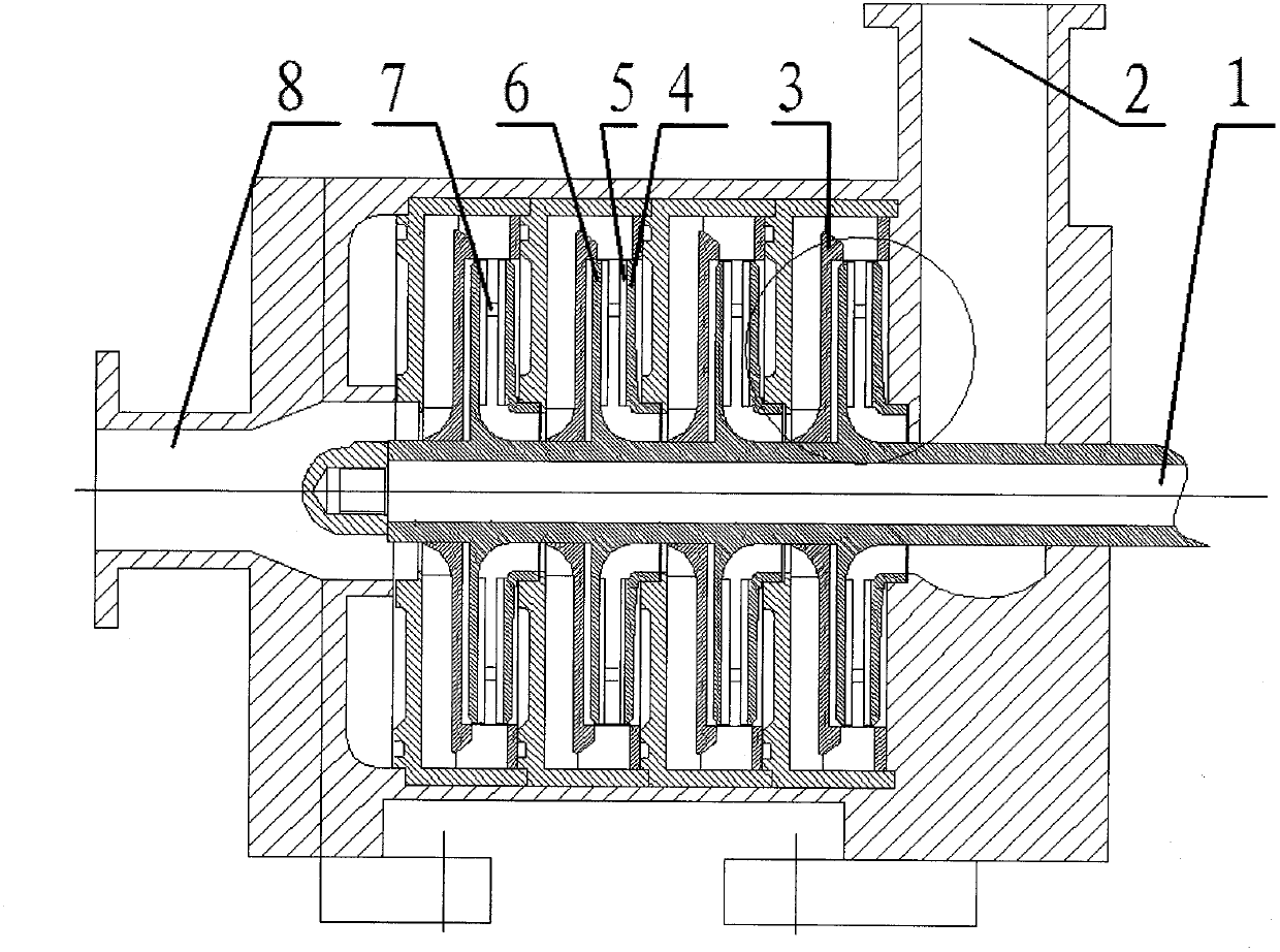
[0023] refer to figure 1 It is a structural diagram of an embodiment of a multi-stage vane mud pump. When the pump is working normally, the subsea motor drives the drive shaft to run, and the drive shaft drives the impeller cover plate to run through the key. The returned drilling fluid and cuttings pass through the multi-stage pump inlet 2, disc The work done by the impeller is further introduced into the guide vane 3, thereby completing a single-stage blade mud pump cycle, and the work is done by the multi-stage unit to reach the required lift of the pump, and finally returns to the sea surface through the return pipeline connected to the pump outlet 8.

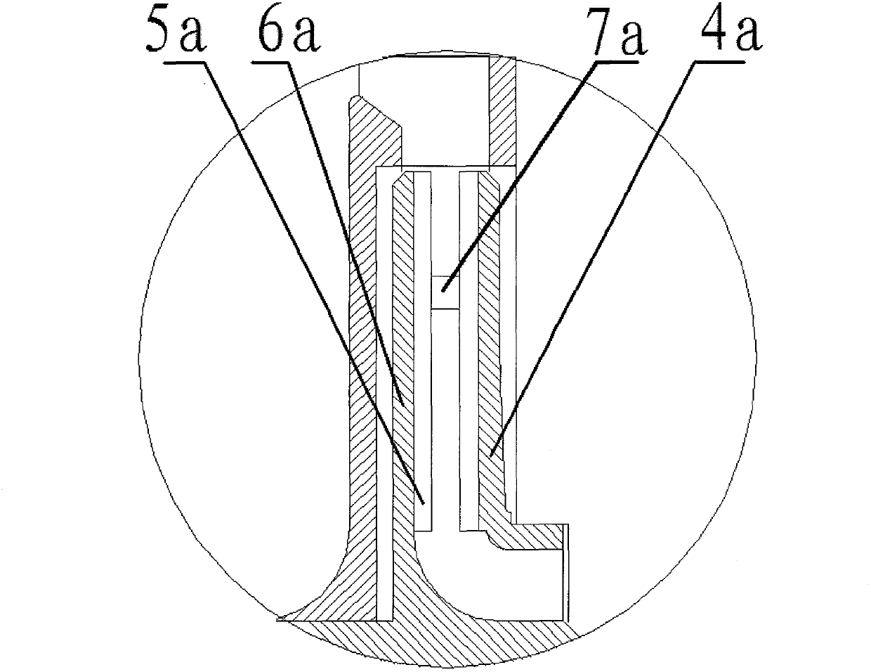
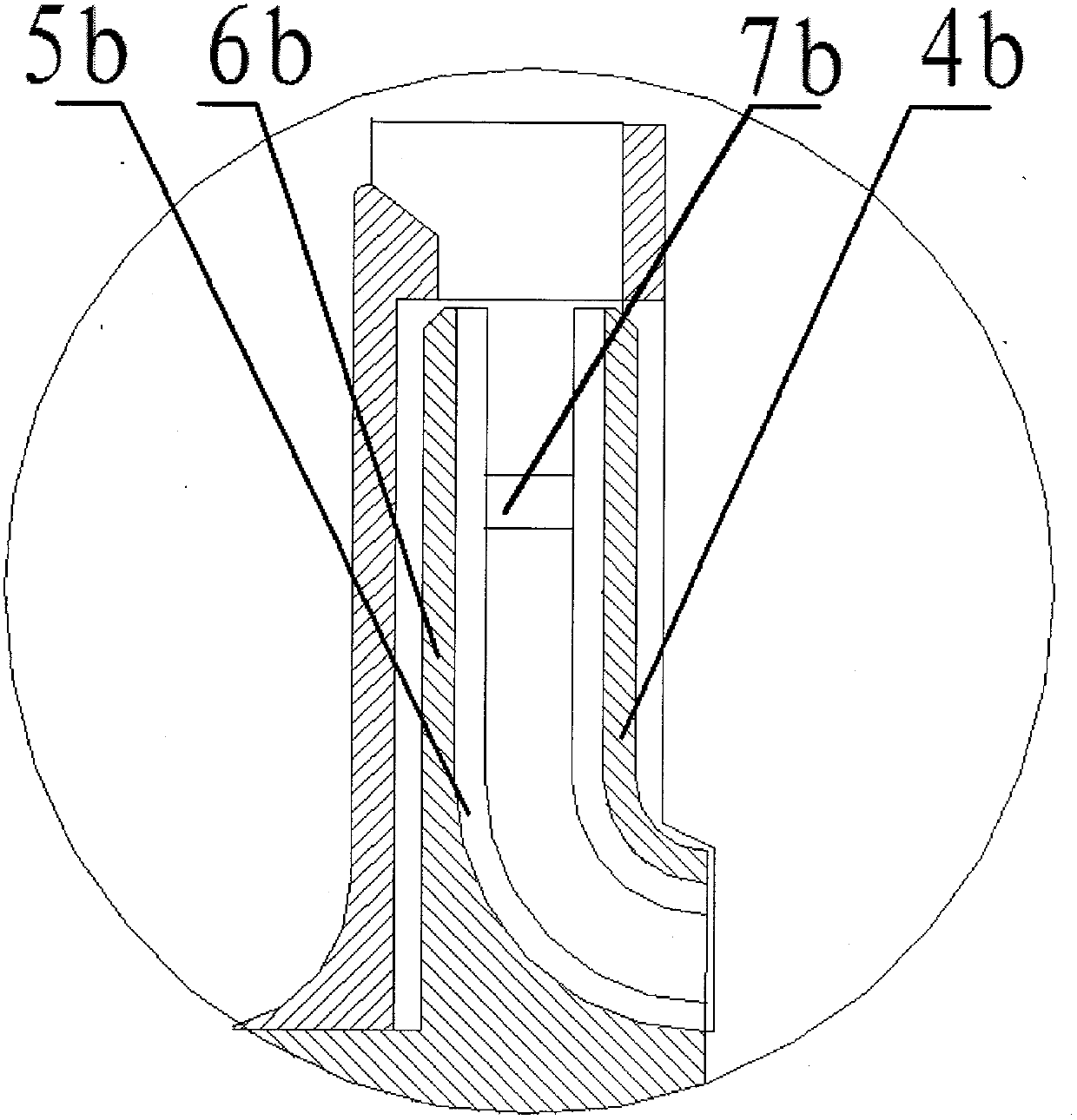
[0024] Because there are radial blades 5 between the driving impeller cover plate 6 and the driven cover plate 4, the flow head performance curve of the single-stage disc impeller is relatively flat,...


PUM


Abstract

The invention discloses a multistage blade mud pump for riserless subsea mudlift drilling. The multistage blade mud pump comprises driving impeller cover plates, driven impeller cover plates, radial blades, guide vanes, a driving shaft and the like. The radial blades are arranged between the driving impeller cover plates and the driven impeller cover plates and are discontinuous, namely a bladeless area is present; the driving impeller cover plates and the driven impeller cover plates are connected through connecting arms; inlet sections of the driving impeller cover plates and the driven impeller cover plates are properly transited to the radial direction in an arc form or a conical form; and a fluid medium is guided to the next stage of impeller through a guide vane. The multistage blade mud pump can deliver multi-phase flow media, is not blocked, and is wear-resistant and high in lift; and a flow-lift performance curve is flat, a working range is wide and the requirement on mechanical sealing property is low.

Description

technical field [0001] The invention relates to the field of fluid conveying machinery, in particular to a multi-stage vane mud pump for lifting drilling mud on the seabed without a riser, which is suitable for conveying drilling mud and other seabed mineral particles on the seabed. Background technique [0002] Riserless mud recovery drilling technology is a realization of dual-gradient drilling technology. The difference from other dual-gradient drilling technologies is that the mud and cuttings returned to the riserless drilling system are returned to the sea surface through the suction module through the subsea mud lift pump, and Pressure control realizes dual-gradient drilling. At present, the return of mud in the riserless drilling system is mainly realized by the series connection of the mud lift pump, and as the water depth increases, the number of series modules of the pump increases, which reduces the reliability and maintainability of the lift pump module; The sp...

Claims


Application Information

Patent Timeline
Patent Type & Authority Applications(China)
IPC IPC(8): F04D7/04F04D1/06F04D29/22
Inventor 陈国明尹树孟周昌静徐长航陈永超吕涛
Owner CHINA UNIV OF PETROLEUM (EAST CHINA)
Why Eureka
Try Eureka