Eureka AIR delivers breakthrough ideas for toughest innovation challenges, trusted by R&D personnel around the world.

Sounding rod debugging device for determining datum point of blast-furnace charge level and debugging and positioning method of device

A technology of blast furnace material surface and positioning method, which is applied to inspection devices and other directions, can solve the problems of inconvenient operation, cumbersome debugging, low accuracy, etc., and achieve the effects of accurate detection of material lines, reduced labor intensity, and convenient and simple debugging.

Inactive Publication Date: 2013-09-18
HEBEI IRON AND STEEL
View PDF3 Cites 15 Cited by
  • Summary
  • Abstract
  • Description
  • Claims
  • Application Information

AI Technical Summary

Problems solved by technology

In the background technology, two probe detection equipment are installed in the blast furnace. When the material level detected by the two probes is quite different, it is impossible to determine whether there is a problem with the material level or the probe detection equipment. Experienced people judge visually (first: visually check whether the material surface is too bad, second: visually check whether the two probes can be aligned with the reference point at the position of the zero material line); if one of the ruler heads falls off, It can only be debugged by referring to the material line depth of another probe, while the other probe is working normally, and the material line display is constantly changing as the material surface moves down. It is very inconvenient to operate, and it must be completed in the fabric gap. Cloth time limit (cloth must be raised), it needs to use multiple cloth intervals to complete the debugging
Debugging by manual visual inspection is limited by the site, light, personnel, etc., the accuracy is low, the error of the zero-point material line is large, and the debugging is cumbersome and affects production.

Method used


Image

  • Sounding rod debugging device for determining datum point of blast-furnace charge level and debugging and positioning method of device

Examples


Embodiment Construction

[0020] The present invention will be further described through the embodiments below in conjunction with the accompanying drawings.

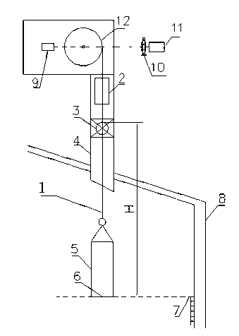
[0021] A probe debugging device for determining the reference point of a blast furnace charge level, comprising a probe pendant 5, an absolute encoder 9, a motor 11, a drum 12, a cable 1, a ball valve 3 and a blast furnace pipe 4, and a ball valve is arranged on the blast furnace pipe. The output of the motor is connected to the drum, one end of the cable is wound on the drum, and the other end of the cable passes through the blast furnace pipe and the ball valve and enters the blast furnace, and is connected with the vertical head of the probe; the motor and the shaft of the drum are provided with an absolute encoder.

[0022] A brake 10 is provided on the motor and drum shaft; a probe inspection hole 2 is provided on the blast furnace pipeline.

[0023] The absolute encoder is a rotary multi-turn absolute encoder.

[0024] In this embodiment,...


PUM


Abstract

The invention relates to a sounding rod debugging device for determining a datum point of a blast-furnace charge level and a debugging and positioning method of the device and belongs to the technical field of blast-furnace sounding rod measurement. According to the technical scheme, the sounding rod debugging device comprises a sounding rod head (5), absolute value encoders (9), a motor (11), a roller (12), a mooring rope (1), a ball valve (3) and a blast-furnace pipeline (4), wherein the ball valve is arranged on the blast-furnace pipeline; the output of the motor is connected with the roller; one end of the mooring rope is wound on the roller, and the other end of the mooring rope penetrates through the blast-furnace pipeline and the ball valve to enter the blast furnace and is connected with the sounding rod head; the absolute value encoders are arranged on the motor and the roller shaft. The sounding rod debugging device has the positive effects that the datum point of a sounding rod does not required to be corrected during blast-furnace blowing-down, the sounding rod can be debugged during normal production, manual visual inspection is not required during determining and debugging, the stock level is accurately detected, the datum point of the charge level can be corrected when the stock level cannot be determined in a production process, the blowing-down is not required in the process of replacing the sounding rod head, the debugging is convenient and simple and is not limited by the blanking time, and the labor intensity is reduced.

Description

technical field [0001] The invention relates to a probe debugging device and a debugging and positioning method for determining a reference point of a blast furnace charge level, and belongs to the technical field of blast furnace probe measurement. Background technique [0002] The blast furnace probe is a material level detection equipment used to detect ore and coke in the blast furnace, which is used for smelting operators to visually observe the release of materials in the furnace, and at the same time control the discharge of ore, coke and other materials into the furnace . When the probe detects that the material in the furnace falls to the set material level, the probe is automatically raised to the stop position, and materials such as ore and coke are discharged into the blast furnace according to the set value of the process flow. After the material is discharged, the probe will be automatically lowered from the stop position at the set speed. After it is lowered ...

Claims


Application Information

Patent Timeline
IPC IPC(8): C21B7/24
Inventor 管宝兴白华周剑锋张春生孟宪义赵军王玉敏
Owner HEBEI IRON AND STEEL
Why Eureka
Eureka Blog
Learn More