
Household bread maker

A technology for household bread machines and bread machines, which can be used in home appliances, toasting devices, and applications. It can solve problems such as skin thickness, uneven color, and excessively dense electric heating tubes, and achieve uniform color, easy operation, and high luster. Good results

Inactive Publication Date: 2013-09-18
卢润侨 +1
View PDF10 Cites 6 Cited by
  • Summary
  • Abstract
  • Description
  • Claims
  • Application Information

AI Technical Summary

Problems solved by technology

The heat source design of existing household bread machines generally adopts a single electric heating tube structure. The electric heating tube surrounds the lower part of the bread barrel and is installed on the inner wall of the baking chamber. The bread produced has uneven color, thick skin, and bad taste. The main reasons are The reason is that the upper part of the bread is relatively underheated. This is because the upper part of the bread is far away from the electric heating tube. The heat reflection of the bread bucket is too strong, and the metal cover lining on the top of the bread bucket for reflecting heat radiation is far away from the electric heating tube, and there is a perspective window in the middle, so the heat reflection is weak
[0003] In view of the above problems, Chinese Patent Publication No. CN 107864 C discloses a bread machine upper cover structure, which is characterized in that a porous metal reflector is added below the see-through window of the cover body, which to a certain extent compensates for the heat lost due to the setting of the see-through window. Reflection, thereafter, Chinese Patent Publication No. CN2257692Y discloses a front-opening double electric heating tube bread machine. Its disadvantage is that the bread bucket cannot be taken out according to normal operation, because the bread bucket needs to be rotated vigorously and then lifted up to be taken out, and the upper part of the baking chamber is closed in the front-opening door structure, so there is no way to leave enough space above the bread bucket. space
In view of this situation, Chinese Patent Publication Nos. CN 201085513Y and CN 201664219 U have successively disclosed a bread machine with double electric heating tubes with the top open. The upper part and the lower part are fixed on the inner wall of the baking chamber, which has the advantage of solving the problem that the bread bucket cannot be taken out, and shortening the distance between the electric heating tube, the upper part of the bread and the lid lining, and improving the heating condition of the upper part of the bread to a certain extent. The disadvantage is that it is still not enough to compensate for the relative lack of heating of the upper part of the bread, because for the sake of not hindering the removal of the bread bucket and safety considerations, the upper electric heating pipe cannot be close to the mouth of the bread bucket, let alone placed on the mouth of the bucket; In addition, two electric heating tubes are arranged around the middle and lower part of the baking chamber, which is inconvenient for cleaning work, especially when cleaning the sundries below, it is easy to be scalded by the electric heating tubes above
The latest solution is the upper-opening single electric heating tube bread machine disclosed in Chinese Patent Publication No. CN101601548 B. The disadvantage of the set of electric heating tube control devices is that it still cannot solve the problem of insufficient heating of the upper part of the bread. Compared with the double electric heating tube bread machine, there is no progress in improving the heating of the upper part of the bread. The problem of burns is more prominent

Method used


Image

  • Household bread maker
  • Household bread maker
  • Household bread maker

Examples


Embodiment Construction

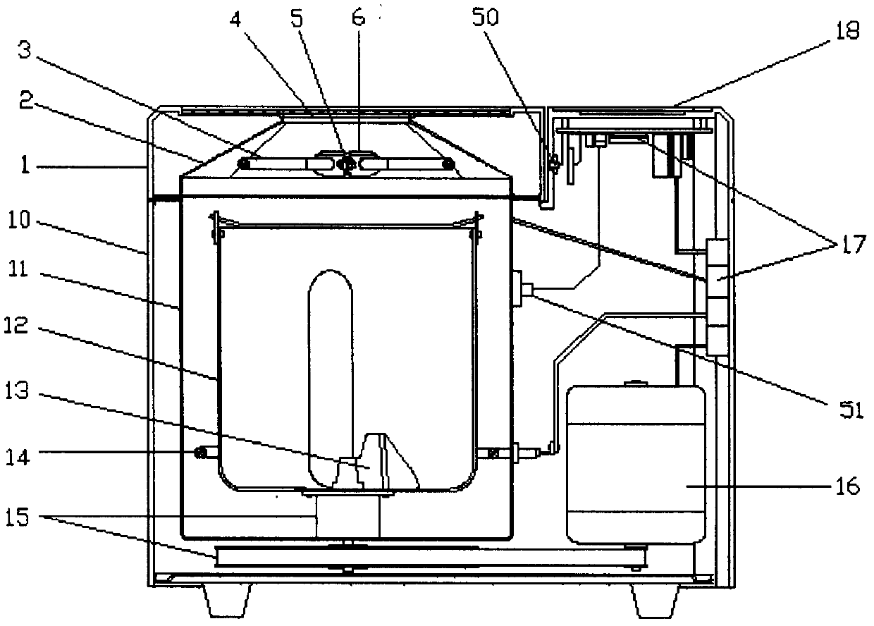
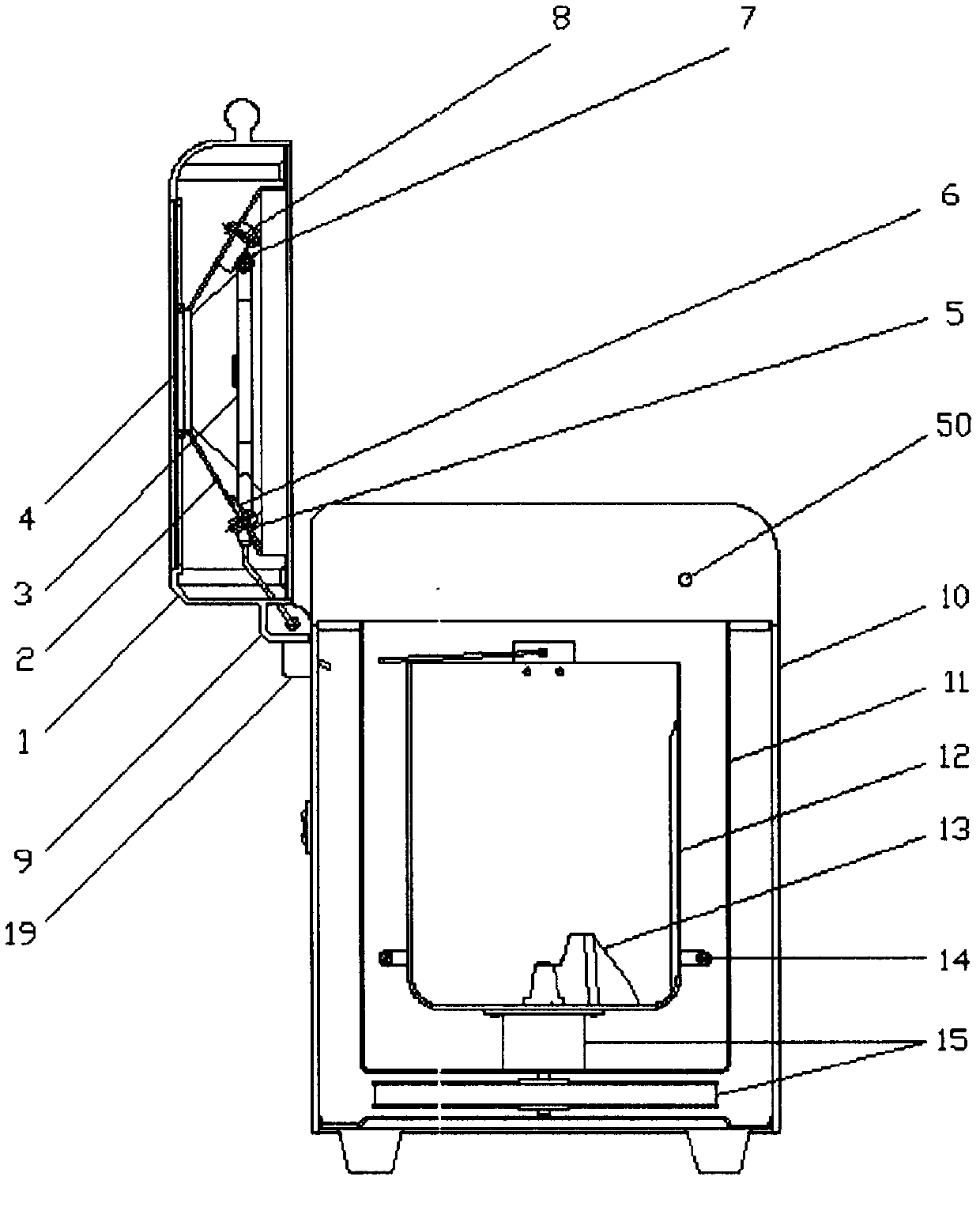
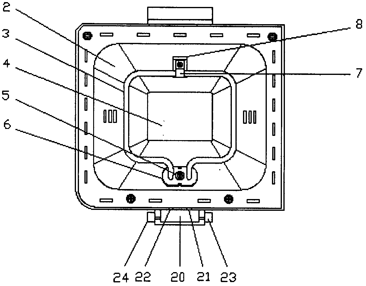
[0019] The present invention will be described in detail below in conjunction with the accompanying drawings and embodiments. As shown in the figure, the household bread machine disclosed by the present invention is a double electric heating pipe bread machine with an upper opening cover. The space between the cavity 11 and the fuselage 10 is provided with a driving motor 16, a transmission device 15 and an electric control device 17, the bread bucket 12 is placed in the lining cavity 11, the bottom of the bread bucket 12 is provided with a stirring blade 13, and the driving motor 16 The transmission device 15 drives the stirring blade 13 to stir the noodles, and the lower electric heating tube 14 surrounds the bread bucket 12 and is fixedly arranged on the lower part of the inner wall of the lining cavity 11; the operation panel 18 is arranged on the top surface of the fuselage 10. The cover body 1 is hinged with the fuselage 10, and the cover body 1 is provided with a cover l...


PUM


Abstract

The invention provides a household bread maker with an upper openable cover and double electric heating pipes. A cover body is hinged with a machine body; an upper open lining cavity formed by a metal plate is formed in the machine body; a bread barrel is arranged in the lining cavity; a lower electric heating pipe is fixedly arranged at the lower part of the lining cavity around the bread barrel; a cover lining formed by a metal plate is arranged in the cover body; an upper electric heating pipe is fixedly arranged inside the cover lining; when the cover body is buckled with the machine body, the upper electric heating pipe is positioned above a barrel opening of the bread barrel; and an electrical connecting wire of the upper electric heating pipe is led into the machine body by a power transmission connecting part of the machine body and the cover body, and is connected with the output end of an upper electric heating pipe control circuit of an electric control device in the machine body. The invention solves the technical problem of insufficient heating for the upper part of bread and the technical problem of safely transmitting power to the upper electric heating pipe arranged in the cover body and provides a safe power transmission connecting structure for a high-power electric device arranged in a split body hinged with a main body. The household bread maker provided by the invention is convenient, safe and reliable to operate and can be used for making bread with uniform fineness, thin skin and better taste and color.

Description

technical field [0001] The invention relates to a bread machine suitable for home use Background technique [0002] Household bread machines can automatically complete operations such as dough mixing, fermentation and baking. The heat source design of existing household bread machines generally adopts a single electric heating tube structure. The electric heating tube surrounds the lower part of the bread barrel and is installed on the inner wall of the baking chamber. The bread produced has uneven color, thick skin, and bad taste. The main reasons are The reason is that the upper part of the bread is relatively underheated. This is because the upper part of the bread is far away from the electric heating tube. The heat reflection of the bread barrel is too strong, and the metal cover lining on the top of the bread barrel for reflecting heat radiation is far away from the electric heating tube, and there is a perspective window in the middle, so the heat reflection is weak....

Claims


Application Information

Patent Timeline
IPC IPC(8): A47J37/08
Inventor 芦雷卢润侨
Owner 卢润侨
Learn More