
Device for achieving multipath serial ADC synchronization by adopting FPGA

A single-channel, analog circuit technology, applied in the field of ADC synchronization devices, can solve the problems of reducing the ADC rate, simplicity, and tight pin allocation.

Inactive Publication Date: 2013-09-11
INST OF ACOUSTICS CHINESE ACAD OF SCI
View PDF7 Cites 23 Cited by
  • Summary
  • Abstract
  • Description
  • Claims
  • Application Information

AI Technical Summary

Problems solved by technology

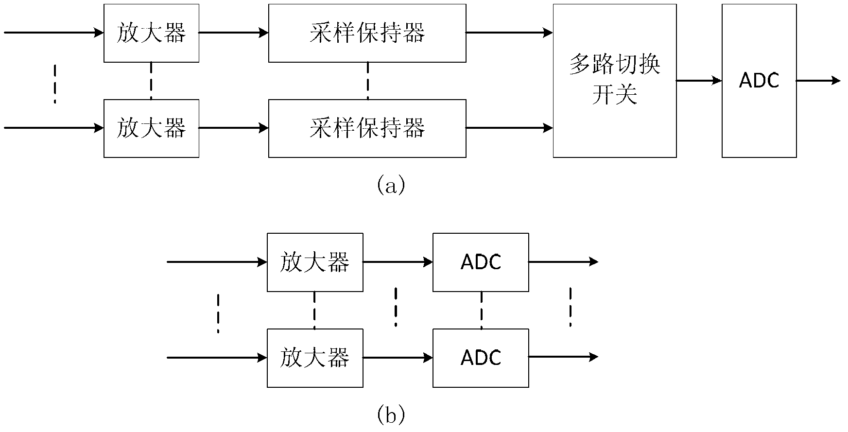
[0005] Obviously, if the two methods use the same ADC, the first method is more economical because the sample-and-hold device is much cheaper than the ADC. But considering the speed, the second method is faster, which means Because the first method needs to convert each signal in turn. Conversely, if the same speed is to be guaranteed, the first method requires a high-speed ADC, which is more expensive, while the second method requires lower ADC requirements. .
[0006] Due to the use of parallel ADC chips in existing solutions, controller chips such as FPGA, DSP, single-chip microcomputers, etc. cannot provide enough pins, so the number of channels cannot be too many; and even if the number of channels increases, if the sampling of different channels The existing methods are also difficult to achieve at all times; the main disadvantages of the existing methods are listed in detail below:
[0007] (1) The use of parallel ADC chips requires a large number of pins, and it is difficult to achieve multi-channel, and when the system needs other functions, the allocation of pins is very tight
[0008] (2) It is difficult to achieve synchronization for multi-channel ADCs. If multiple signals use the same ADC, using a multi-channel switch to switch between different channels will also reduce the sampling rate of the ADC.
[0010] (4) The design of the ADC control system is old-fashioned and simple, without incorporating new design methods to improve performance, easy to be imitated and uncompetitive

Method used


Image

  • Device for achieving multipath serial ADC synchronization by adopting FPGA
  • Device for achieving multipath serial ADC synchronization by adopting FPGA
  • Device for achieving multipath serial ADC synchronization by adopting FPGA

Examples


Embodiment Construction

[0031] In order to make the object, technical solution and advantages of the present invention clearer, the present invention will be further described in detail below in conjunction with the accompanying drawings and embodiments. It should be understood that the specific embodiments described here are only used to explain the present invention, not to limit the present invention.

[0032] Below in conjunction with accompanying drawing, the present invention is described in detail.

[0033] From image 3 We can see that this design is mainly composed of programmable logic modules (2 and 3 in the figure are programmed by programmable logic modules) and an array composed of AD analog-to-digital conversion modules (1 in the figure is an array composed of AD analog-to-digital conversion modules , the array is composed of multiple single-channel ADCs) composed of two parts, the interface between the FPGA as the control chip and the ADC array is completely digital signal, the inter...


PUM


Abstract

The invention discloses a device for achieving multipath serial ADC synchronization by adopting an FPGA. The device comprises an ADC analog circuit module, an ADC data acquisition module and a data caching module, wherein the ADC analog circuit module is used for converting external input analog signals into digital signals and transmitting the converted digital signals to the ADC data acquisition module, and is composed of multiple single-path ADC analog circuit modules, the ADC data acquisition module is used for synchronously controlling the ADC analog circuit module, acquiring the converted digital signals of the ADC analog circuit module, converting the serial digital signals to be parallel and transmitting parallel ADC data to the data caching module, and the data caching module is used for receiving and caching the parallel ADC data transmitted by the ADC data acquisition module 2, and the parallel ADC data are prepared to be used and processed by equipment of a next stage. The device is high in technical content and strong in confidentiality.

Description

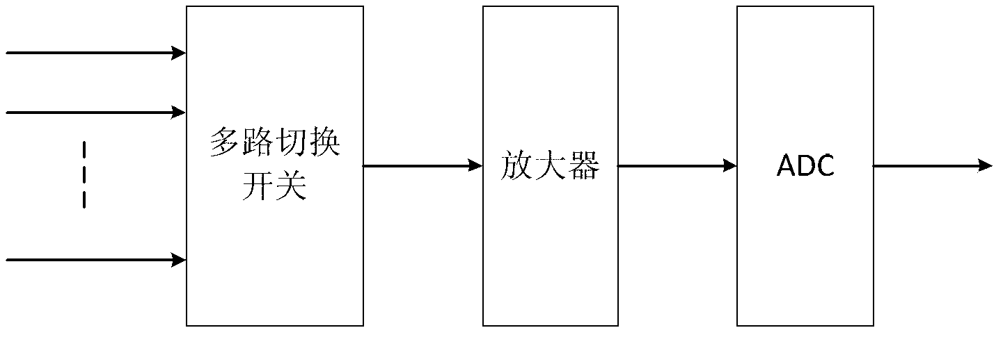
technical field [0001] The invention relates to the field of signal acquisition, in particular to a device for realizing ADC synchronization by using FPGA. Background technique [0002] Multi-channel data acquisition systems are widely used in sonar, radar and other fields. Array signal processing requires data information at different locations in space; multi-channel data acquisition systems are also used in other occasions that require multi-node and multi-channel data acquisition, such as agriculture, Meteorology and other fields require information such as temperature and humidity in different locations. [0003] The first multi-channel synchronous data acquisition such as figure 1 As shown, when collecting multi-channel data, each input signal is connected to the ADC through a multi-channel switch, which is time-sharing sampling. In time-division sampling, only one input signal enters the ADC for conversion at any time, so this method is only suitable for occasions w...

Claims


Application Information

Patent Timeline
IPC IPC(8): H03M1/54
Inventor 马晓川鄢社锋林津丞杨力彭承彦王敏
Owner INST OF ACOUSTICS CHINESE ACAD OF SCI
Learn More