Pulse signal acquisition circuit
A pulse signal and acquisition circuit technology, which is applied in the direction of logic circuit connection/interface layout, etc., can solve the problems of damaged circuits or components, terminals that cannot correctly collect electric energy meter pulses, and wrong connections.
- Summary
- Abstract
- Description
- Claims
- Application Information
AI Technical Summary
Problems solved by technology
Method used
Image

Examples
Embodiment 1
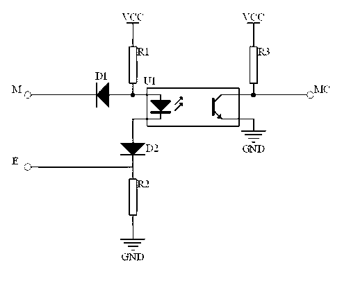
[0026] Such as figure 1 As shown, a pulse signal acquisition circuit of the present invention, the pulse acquisition circuit includes an input pulse signal and an output pulse signal, and the input pulse signal is shaped into an output pulse signal by a pulse shaping circuit, wherein the input pulse signal and the pulse An overvoltage protection circuit is provided between the shaping circuits. In this embodiment, the pulse shaping circuit includes an optocoupler U1, the input pulse signal includes an input pulse signal M and an input pulse signal E, the input pulse signal M is connected to the anode of the optocoupler U1, and the input pulse signal E is connected to the cathode of optocoupler U1.
[0027] In this embodiment, the overvoltage protection circuit includes a reverse diode D1 disposed between the input pulse signal M and the optocoupler, and a reverse diode D2 disposed between the input pulse signal E and the optocoupler. The cathode of the reverse diode D1 is co...
Embodiment 2
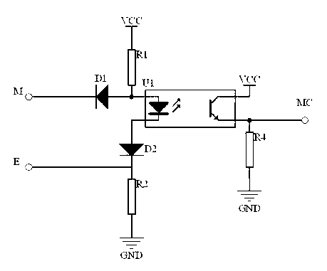
[0031] Such as figure 2 As shown, the difference between this embodiment and the above-mentioned Embodiment 1 is that the emitter of the optocoupler U1 is connected to the output pulse signal MC, the emitter of the optocoupler U1 is provided with a pull-down resistor R4, and the optocoupler U1 The emitter is electrically connected to the weak power supply VCC.
[0032] By setting the pulse shaping circuit, the pulse input signal is shaped and then output to the pulse signal acquisition device, so that the pulse signal acquisition device can accurately and effectively complete the pulse signal detection of the electric energy meter. At the same time, the optocoupler is used for shaping, so that the input pulse signal and the output pulse signal are completely isolated while the shaping conversion is completed, that is, the energy meters are isolated, and the high-voltage signal at the end of the energy meter is avoided. Pulse signal acquisition The device forms a voltage shoc...
PUM
 Abstract
Description
Claims
Application Information
 - Generate Ideas
- Intellectual Property
- Life Sciences
- Materials
- Tech Scout
- Unparalleled Data Quality
- Higher Quality Content
- 60% Fewer Hallucinations
Browse by: Latest US Patents, China's latest patents, Technical Efficacy Thesaurus, Application Domain, Technology Topic, Popular Technical Reports.
© 2025 PatSnap. All rights reserved.Legal|Privacy policy|Modern Slavery Act Transparency Statement|Sitemap|About US| Contact US: help@patsnap.com