
Ripple modulation compensation method for input voltage of single-phase inverter

A single-phase inverter, input voltage technology, applied in the direction of electrical components, output power conversion devices, etc., can solve the problem of poor compensation effect, reduce the influence of input voltage ripple, reduce control time, and increase costs. Effect

Inactive Publication Date: 2013-09-11
BEIJING EPSOLAR TECH
View PDF1 Cites 5 Cited by
  • Summary
  • Abstract
  • Description
  • Claims
  • Application Information

AI Technical Summary

Problems solved by technology

In this compensation method, as the effective value of the input voltage deviates from the rated input voltage, the compensation effect will become worse, and there is always a time delay of one carrier cycle

Method used


Image

  • Ripple modulation compensation method for input voltage of single-phase inverter
  • Ripple modulation compensation method for input voltage of single-phase inverter
  • Ripple modulation compensation method for input voltage of single-phase inverter

Examples


Embodiment Construction

[0024] The present invention will be further described below in conjunction with specific embodiments and accompanying drawings.

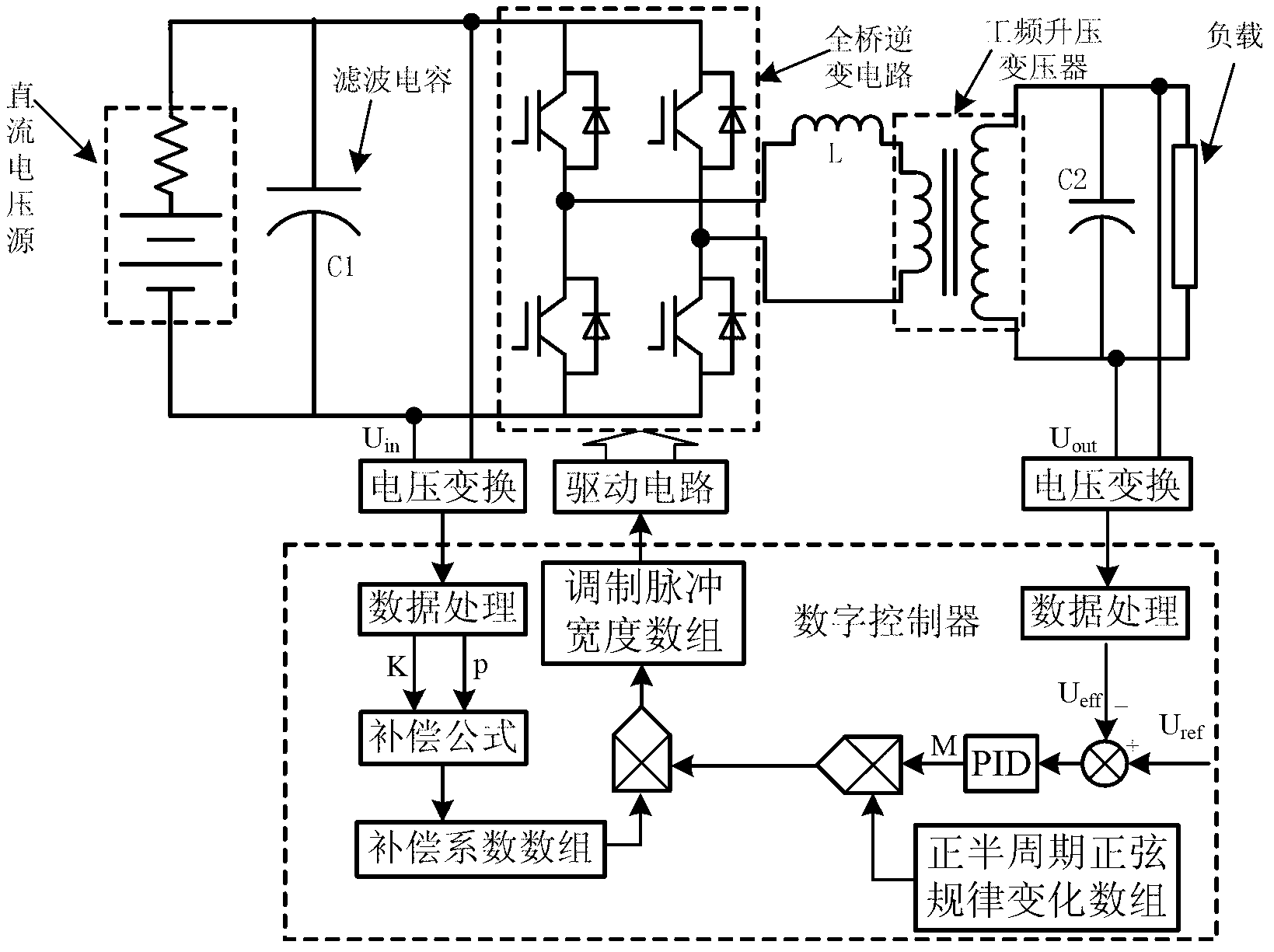
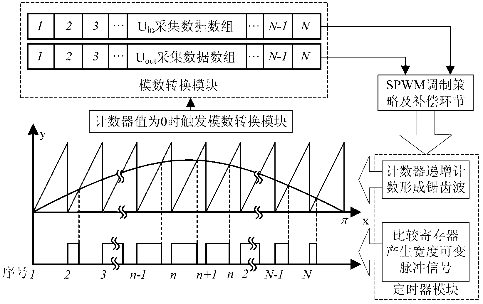
[0025] Such as figure 2 As shown, the inverter system includes a DC voltage source composed of a lead-acid battery, an input filter capacitor, a single-phase full-bridge MOSFET inverter circuit, a power frequency step-up transformer, and a digital control system composed of an LM4F230 microprocessor and peripheral chips. device and other parts. The rated input voltage range is 20V~32V, the rated output voltage is 220V±5%, and the rated output frequency is 50Hz±0.5Hz. The clock frequency of the digital controller timer module is 80MHz, and the array length N is 256. At this time, the switching frequency of the inverter circuit is 25.6kHz, and the amplitude of the positive half-cycle sine law changes the array, that is, the maximum value of the timer count is 3125.

[0026] Aiming at the compensation link of the input voltage ripple of the full-b...


PUM


Abstract

A ripple modulation compensation method for input voltage of a single-phase inverter includes: inverter output voltage and full-bridge inverter circuit input voltage are collected while modulating pulse is output; SPWM (sinusoidal pulse width modulation) pulse signals are obtained by processing the inverter output voltage; ripple parameters are extracted from the full-bridge inverter circuit input voltage; according to pulse widths of the ripple parameter compensation SPWM signals, output voltage harmonic caused by ripples can be eliminated from compensated modulation. The method has the advantages that a modulation strategy is compensated only in software, so that hardware cost is saved; input voltage ripple parameters are compensated directly, so that ripple influence can be inhibited effectively and output quality of an inverter system is improved.

Description

technical field [0001] The invention belongs to the field of inverter control, and relates to a modulation and compensation method for input voltage ripple of a full-bridge inverter circuit of a single-phase inverter. Background technique [0002] When the single-phase inverter is used in practice, due to its own structure, the voltage at the input terminal of the full-bridge inverter circuit will have a low-frequency ripple that is twice the output frequency, and the ripple amplitude will increase with the increase of the inverter load. However, the position of the ripple peak relative to the starting point of the modulation signal moves when the load impedance changes. [0003] Sinusoidal pulse width modulation (SPWM) modulation strategy is based on the premise of constant voltage at the input end of the full-bridge inverter circuit, so the ripple in the input voltage will affect the quality of the inverter output voltage, so that the fundamental wave is superimposed on th...

Claims


Application Information

Patent Timeline
IPC IPC(8): H02M1/14
Inventor 孙本新万江文苑海涛冯仁剑卢耀文
Owner BEIJING EPSOLAR TECH
Learn More