
Low-speed gear information case body

A gear and box technology, applied in the field of low-speed gear information boxes, can solve the problems of high hardware requirements, difficult diagnosis, and difficult identification of the acoustic emission method, and achieve improved detection accuracy and efficiency, low energy consumption detection and diagnosis, and box The effect of simple structure

Active Publication Date: 2013-09-11
CHONGQING UNIV +1
View PDF5 Cites 3 Cited by
  • Summary
  • Abstract
  • Description
  • Claims
  • Application Information

AI Technical Summary

Problems solved by technology

[0002] Existing low-speed gearboxes usually only have the box body itself. In order to diagnose the fault of the box body, vibration measurement, oil analysis method and acoustic emission method are usually used. For the vibration measurement method, due to the low speed of the low-speed gearbox, The impact energy caused by gear failure is small, and its vibration signal is not obvious
At the same time, helical gears and spiral bevel gears have a large load-bearing capacity, and minor faults have little impact on the vibration of their systems. Therefore, the current diagnostic methods based on vibration are difficult to identify and diagnose.
However, the oil analysis method is difficult to realize real-time diagnosis due to the lag of sampling analysis, which affects the ability of early diagnosis of faults
However, the acoustic emission method has high requirements on hardware and is easily disturbed by external factors, so the diagnostic success rate is not high.

Method used


Image

  • Low-speed gear information case body
  • Low-speed gear information case body
  • Low-speed gear information case body

Examples


Embodiment Construction

[0030] The specific implementation manner and working principle of the present invention will be further described in detail below in conjunction with the accompanying drawings.

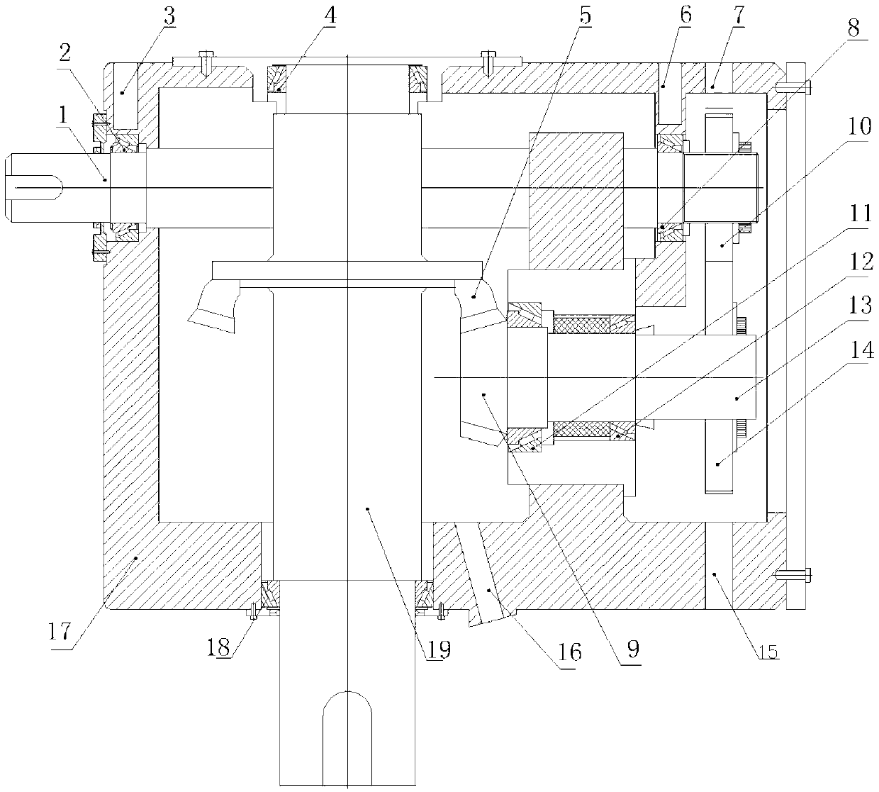
[0031] Such as figure 1 As shown, a low-speed gear information box includes a box 17, a high-speed input shaft 1, an intermediate shaft 13, and a low-speed output shaft 19, and a first tapered roller shaft is horizontally arranged on the left and right sides of the box 17. 2 and the second tapered roller shaft 8, the third tapered roller shaft 11 and the fourth tapered roller shaft 12 are arranged horizontally on the middle support wall of the box body 17, and are arranged longitudinally on the front and rear sides of the box body 17 There are fifth tapered roller shaft 4 and sixth tapered roller shaft 18;

[0032] The high-speed input shaft 1 is installed on the first tapered roller shaft 2 and the second tapered roller shaft 8, and the high-speed input shaft 1 is supported by the first tapered rol...


PUM

PropertyMeasurementUnit
Diameteraaaaaaaaaa

Abstract

The invention discloses a low-speed gear information case body. The low-speed gear information case body comprises a case body, a high-speed input shaft, an intermediate shaft, a low-speed output shaft, a tapered roller shaft, a primary transmission pinion wheel, a primary transmission gearwheel, a secondary transmission pinion wheel and a secondary transmission gearwheel and is characterized in that a first vibration detecting hole, a second vibration detecting hole and a first gear impulse detecting hole are formed in the rear wall of the case body; a second gear impulse detecting hole and a gear displacement detecting hole are formed in the front wall of the case body; a vibration detector is mounted in the vibration detecting hole; an impulse detector is mounted in the gear impulse detecting hole; and a displacement detector is mounted in the gear displacement detecting hole. The remarkable effects of the low-speed gear information case body are as follows: the structure of the case body is simple; the arrangement is reasonable; detecting points and detecting equipment are accurately selected; high-precision, low-cost and energy-efficient detection and diagnosis to the early failures of a low-speed gearbox are realized; and the detecting precision and efficiency of the failures of the low-speed gearbox are improved.

Description

technical field [0001] The invention relates to a gear box, in particular to a low-speed gear information box. Background technique [0002] Existing low-speed gearboxes usually only have the box body itself. In order to diagnose the fault of the box body, vibration measurement, oil analysis method and acoustic emission method are usually used. For the vibration measurement method, due to the low speed of the low-speed gearbox, The impact energy caused by gear failure is small, and its vibration signal is not obvious. At the same time, helical gears and spiral bevel gears have a large load-bearing capacity, and minor faults have little impact on the vibration of their systems. Therefore, the current diagnostic methods based on vibration are difficult to identify and diagnose. However, the oil analysis method is difficult to realize real-time diagnosis because of the lag in sampling and analysis, which affects the ability of early diagnosis of faults. However, the acoustic ...

Claims


Application Information

Patent Timeline
IPC IPC(8): F16H57/02F16H57/038G01B7/02G01H11/08G01M13/02
Inventor 邵毅敏苏代忠
Owner CHONGQING UNIV
Learn More