Liquid purification device

A liquid purification device and liquid technology, applied in the field of liquid devices, can solve problems such as regular removal, and achieve the effect of suppressing accumulation in a container and saving removal work.

Inactive Publication Date: 2015-09-09
JPC
View PDF8 Cites 0 Cited by
  • Summary
  • Abstract
  • Description
  • Claims
  • Application Information

AI Technical Summary

Problems solved by technology

However, in the case of using such a solid-liquid separation method using a settling tank, it is necessary to periodically remove the sludge deposited in the settling tank, and to remove the sludge adhering to the bottom of the settling tank, regular cleaning of the bottom surface is required.

Method used


Image

  • Liquid purification device
  • Liquid purification device
  • Liquid purification device

Examples


Embodiment Construction

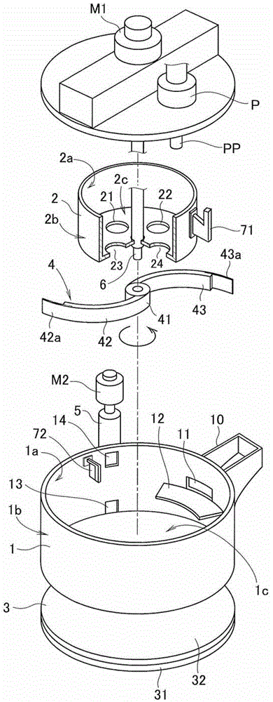
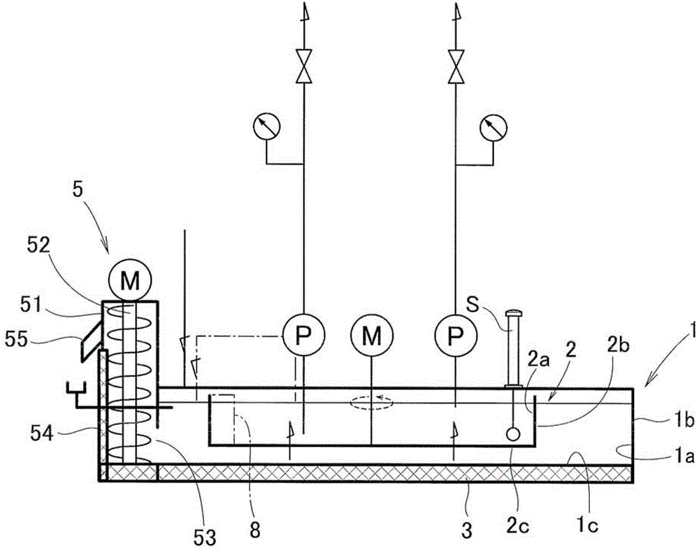
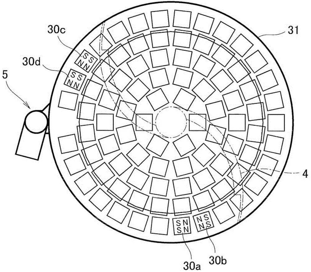
[0039] Hereinafter, embodiments of the present invention will be described based on the drawings. figure 1 It is a figure which shows the outline of embodiment of this invention. As shown in this figure, in this embodiment, a circular bottomed cylindrical second container 2 having a circular cross-sectional shape is arranged inside a bottomed cylindrical first container 1 having a circular cross-sectional shape. A magnetic field applying unit 3 is provided on the lower part of the bottom surface 1c of 1, and a scraper (guiding unit) 4 is provided on the lower part of the bottom surface 2c of the second container 2. In addition, a sludge recovery unit (recovery means) 5 is provided together outside the first container 1 .

[0040] The first container 1 is provided with an inflow portion 10 for receiving the inflow of turbid liquid, and an inflow port 11 for flowing into the inside of the container 1 from the inflow portion 10. In addition, on the inner surface 1a of the side w...


PUM


Abstract

The invention provides a liquid purification device capable of reducing installation area and omitting operations of removing sludge and cleaning. The device includes a first container (1) containing sludge liquid, a second container (2) in the first container and keeping a proper height from the bottom surface of the first container, communication ports (21,22,23,24) arranged in the bottom surface of the second container and communicating with the first container, a magnetic field applying unit (3) generating magnetic field in a plurality of areas of the bottom of the first container (1c), a guide unit (4) flexibly connected with the bottom of the first container and guiding sludge to the side wall of the first container, and a sludge recovery unit (5) arranged at at least one part of the side wall of the first container.

Description

technical field [0001] The present invention relates to a liquid purifying device, and more particularly to a device for purifying liquids such as coolant used in machine tools. Background technique [0002] Metal shavings generated during grinding etc. are mixed in liquids such as coolants used in machine tools such as grinding apparatuses, so attempts have been made to remove the metal shavings (magnets) from the liquid by magnetically attracting them (see Patent Document 1 and 2). However, since abrasive grains and the like are mixed in liquids such as coolants used in grinding machines and the like in addition to metal chips, further filtration is required. Therefore, the applicant of the present invention has developed a filtration device that removes fine sludge in two steps of primary filtration and secondary filtration (see Patent Document 3). [0003] patent documents [0004] Patent Document 1: Japanese Unexamined Patent Publication No. 2003-285238 [0005] Pat...

Claims


Application Information

Patent Timeline
Patent Type & Authority Patents(China)
IPC IPC(8): B24B55/12B24B57/00
CPCY02P70/10
Inventor 井上丰
Owner JPC
Why Eureka
Try Eureka