Method and device for supplying zinc gas

A gas heating device and gas technology, applied in chemical instruments and methods, transportation and packaging, inorganic chemistry, etc., can solve problems such as the inability to produce zinc gas, achieve the effect of suppressing energy consumption and simple control

Inactive Publication Date: 2013-09-04
JNC CORP +2
View PDF3 Cites 4 Cited by
  • Summary
  • Abstract
  • Description
  • Claims
  • Application Information

AI Technical Summary

Problems solved by technology

However, in the device of this structure, although zinc can be evaporated continuously, as mentioned above, it is impossible to generate overheated zinc gas.
Furthermore, this document neither discloses nor suggests a method of supplying superheated zinc gas while controlling the supply speed.
Moreover, in this device, since a graphite crucible or a graphite sleeve is used, carbon is mixed in the zinc gas, which is not good.

Method used


Image

  • Method and device for supplying zinc gas
  • Method and device for supplying zinc gas
  • Method and device for supplying zinc gas

Examples


example

[0112] Hereinafter, the present invention will be described more specifically by way of examples, but the scope of the present invention is not limited to these examples.

example 1

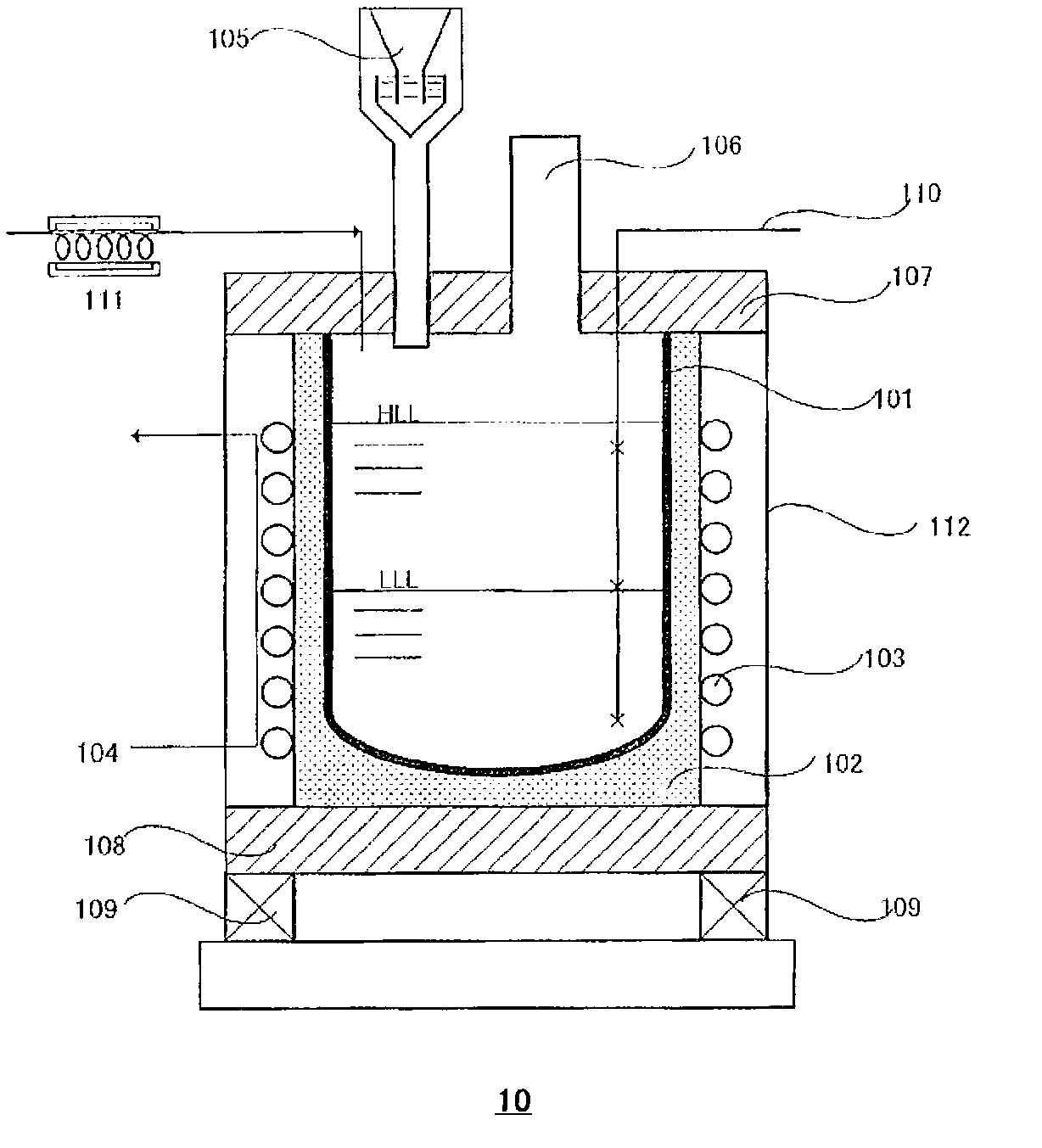
[0114] The zinc gas evaporator 10 used includes: an opaque quartz crucible 101 with an outer diameter of 460 mm, an inner diameter of 400 mm, a radius of curvature of 230 mm, and a height of 750 mm; and an induction coil 103 with a height of 500 mm and an inner diameter of 550 mm. The crucible 101 is placed on a bottom plate 108 made of silica-alumina low-cement castable material. The surrounding of the crucible 101 is insulated by silica sand, and a quartz evaporator cover 107 is installed, and the upper part is covered by a ceramic fiber board. And placed on the weighing device (floor scale) 109 . High-frequency induction heating uses a frequency of 500 Hz and a power supply with an output of 600 kW.

[0115] 330 kg of molten zinc at 450° C. was introduced into such a zinc gas evaporator 10 , and heated to the boiling point by high-frequency induction heating. The approximate formula for the relationship between the input power and the weight reduction rate (zinc evaporatio...

example 2

[0117] Using the same apparatus as in Example 1, the change in apparatus efficiency K when the liquid level of molten zinc was changed was determined. show the result in Figure 6 . The device efficiency K has almost no change when the liquid level of the molten zinc is above 50% of the liquid level. If the liquid level of the molten zinc is lower than 40% of the liquid level, a significant increase in the device efficiency K can be seen. reduce. If it is maintained at a range above 40% of the liquid level position of molten zinc, the change of device efficiency K is not obvious, and zinc gas can be generated by controlling the input power. In the range above 50% of the height position, induction heating can be performed with high precision.


PUM

PropertyMeasurementUnit
diameteraaaaaaaaaa

Abstract

The invention provides a method and device for supplying, at a controlled supply speed, zinc gas which is overheated to above the boiling point of zinc. The method for supplying zinc gas according to the present invention comprises: a step of introducing a zinc melt into a zinc gas evaporator; a step of inputting power corresponding to the supply speed of zinc gas and causing zinc to self-evaporate by high frequency induction heating to generate zinc gas from the zinc melt; a step of introducing the generated zinc gas into a gas heating device; and a step of heating the zinc gas by resistance heating to produce overheated zinc gas. The device for supplying zinc gas according to the present invention is used for the above method, and comprises a zinc gas evaporator, a gas heating device and a control device.

Description

technical field [0001] The invention relates to a method and device for supplying zinc gas. More particularly, it relates to a method and apparatus for supplying superheated zinc gas at a controlled supply rate. Background technique [0002] In recent years, there has been increasing interest in solar power generation as a technology to meet new power demands in order to prevent global warming. In photovoltaic power generation, the method of utilizing solar cells using single crystal silicon or polycrystalline silicon is the mainstream, and in response to the expected rapid increase in demand for photovoltaic power generation devices, it is required to supply large quantities of high-purity silicon as a main material at low cost. [0003] Today, commercially available high-purity silicon is produced by the Siemens process. This method is a method in which the proportion of electric power cost in the manufacturing cost is relatively large, and the production efficiency is l...

Claims


Application Information

Patent Timeline
Patent Type & Authority Applications(China)
IPC IPC(8): C01B33/033F27B14/06F27B14/20C22B19/16
CPCC01B33/021F27B14/061F27B14/20Y10T137/0391Y10T137/6416C22B19/16F27B14/06
Inventor 大久保秀一渊上俊光岩田好喜
Owner JNC CORP
Why Eureka
Try Eureka