Water-saving toilet bowl
A technology for toilets and waterways, applied in flushing toilets, water supply devices, indoor sanitary pipeline installations, etc., can solve problems such as low wastewater reuse rate, inconvenient wastewater collection, and energy consumption
- Summary
- Abstract
- Description
- Claims
- Application Information
AI Technical Summary
Problems solved by technology
Method used
Image
Examples
Embodiment 1
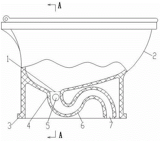
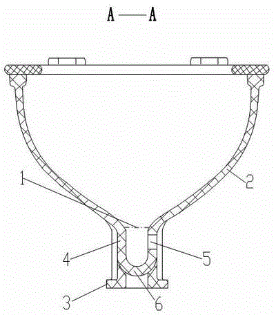
[0017] Embodiment 1: (see figure 1 , figure 2 ) A water-saving toilet, comprising a basin body 2 of the toilet and a drainage pipe 6, the bottom of the basin body 2 communicates with the drainage pipe 6; it is characterized in that: between the upper end surface 1 of the drainage pipe inlet and 200mm below it Water inlet holes 5 are provided on the pipe wall 4 of the discharge pipe between them.
[0018] Usage method: waste water can be discharged into the discharge pipe 6 through the water inlet hole 5 to flush the toilet.
Embodiment 2
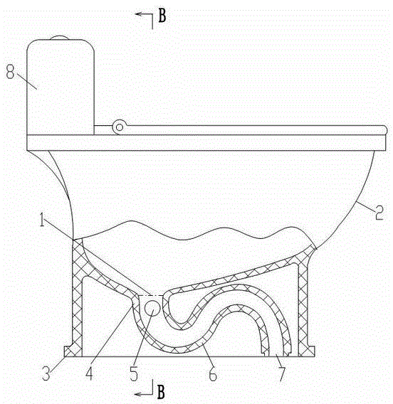
[0019] Embodiment 2: (see image 3 , Figure 4 ) A water-saving toilet, comprising a basin body 2 of the toilet and a drainage pipe 6, the bottom of the basin body 2 communicates with the drainage pipe 6; it is characterized in that: between the upper end surface 1 of the drainage pipe inlet and 200mm below it Water inlet holes 5 are provided on the pipe wall 4 of the discharge pipe between them.
[0020] The preferred structure is: a water inlet hole 5 is provided on the pipe wall 4 of the discharge pipe between the upper end surface 1 of the discharge pipe inlet and 160 mm below it.
[0021] A flushing water tank 8 is provided at the rear of the top of the basin body 2; an annular water channel 9 is provided inside the convex edge of the top of the basin body 2, and a discharge hole 10 facing the inner wall of the basin body 2 is provided at the bottom of the annular water channel 9 , the drain outlet of the flushing water tank 8 communicates with the annular water channel...
Embodiment 3
[0023] Embodiment 3: (see image 3 , Figure 4 ) A water-saving toilet, comprising a basin body 2 of the toilet and a drainage pipe 6, the bottom of the basin body 2 communicates with the drainage pipe 6; it is characterized in that: between the upper end surface 1 of the drainage pipe inlet and 200mm below it Water inlet holes 5 are provided on the pipe wall 4 of the discharge pipe between them.
[0024] The preferred structure is: a water inlet hole 5 is provided on the pipe wall 4 of the discharge pipe between the upper end surface 1 of the discharge pipe inlet and 160 mm below it. A water inlet hole 5 is provided on the pipe wall 4 of the discharge pipe between the upper end face 1 of the discharge pipe inlet and 120 mm below it.
[0025] A flushing water tank 8 is provided at the rear of the top of the basin body 2; an annular water channel 9 is provided inside the convex edge of the top of the basin body 2, and a discharge hole 10 facing the inner wall of the basin bod...
PUM
 Abstract
Description
Claims
Application Information
 - R&D
- Intellectual Property
- Life Sciences
- Materials
- Tech Scout
- Unparalleled Data Quality
- Higher Quality Content
- 60% Fewer Hallucinations
Browse by: Latest US Patents, China's latest patents, Technical Efficacy Thesaurus, Application Domain, Technology Topic, Popular Technical Reports.
© 2025 PatSnap. All rights reserved.Legal|Privacy policy|Modern Slavery Act Transparency Statement|Sitemap|About US| Contact US: help@patsnap.com


