Kipp's generator
A technology of Kip generator and reaction vessel, which is applied in the direction of gas generating devices, chemical instruments and methods, chemical/physical processes, etc. It can solve problems such as inconvenient operation, bursting of reaction vessels, and separation of solid reactants, so as to save reaction liquid, reduce waste, and reduce damage
- Summary
- Abstract
- Description
- Claims
- Application Information
AI Technical Summary
Problems solved by technology
Method used
Image

Examples
Embodiment 1
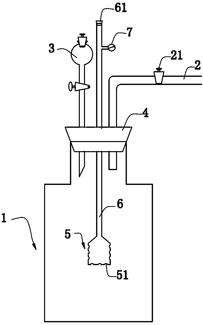
[0019] figure 1 A schematic structural diagram of the Kip generator provided in this embodiment is shown, and for the convenience of description, this figure only provides structural parts related to the present invention.
[0020] Kipp generator comprises reaction vessel 1, air duct 2 and separating funnel 3, and the top of reaction vessel 1 is open, and reaction vessel 1 can be a kind of in jar, test tube etc., and the open end of reaction vessel 1 is covered with There is a rubber stopper 4, the bottom end of the separatory funnel 3 and the air guide tube 2 respectively pass through the rubber stopper 4 and extend into the reaction vessel 1, thereby communicating with the reaction vessel 1, the air guide tube 2 is provided with a rotary piston 21; A solid object holding bottle 5 is provided, and the bottom and side of the solid object holding bottle 5 are provided with a plurality of through holes 51. The top of the solid object holding bottle 5 is connected with a feeding ...
Embodiment 2
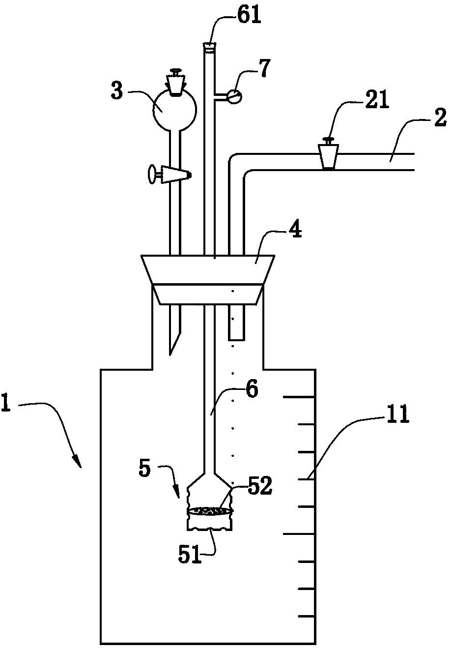
[0022] figure 2 A schematic structural diagram of the Kip generator provided in this embodiment is shown, and for the convenience of description, this figure only provides structural parts related to the present invention.
[0023] The Kipp generator includes a reaction vessel 1, an air duct 2 and a separatory funnel 3. The top of the reaction vessel 1 is open, and the reaction vessel 1 can be a jar, a test tube, etc., and the outer wall of the reaction vessel 1 is provided with a scale 11. The open end of the reaction vessel 1 is covered with a rubber stopper 4, and the bottom end of the separatory funnel 3 and the air guide tube 2 respectively extend into the reaction vessel 1 through the rubber stopper 4, thereby communicating with the reaction vessel 1, and the upper end of the air guide tube 2 A rotary piston 21 is provided; a solid object storage bottle 5 is provided in the reaction vessel 1, and a plurality of through holes 51 are provided on the bottom and side of the...
Embodiment 3
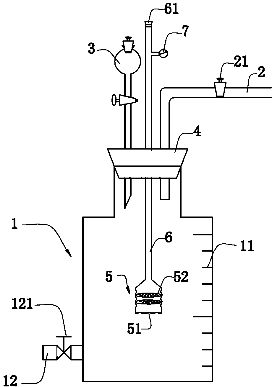
[0025] image 3 A schematic structural diagram of the Kip generator provided in this embodiment is shown, and for the convenience of description, this figure only provides structural parts related to the present invention.
[0026] The Kipp generator includes a reaction vessel 1, an air duct 2 and a separatory funnel 3. The top of the reaction vessel 1 is open, and the reaction vessel 1 can be a jar, a test tube, etc., and the outer wall of the reaction vessel 1 is provided with a scale 11. The bottom of the reaction vessel 1 is provided with a reaction solution outlet 12, and the reaction solution outlet 12 is provided with a control valve 121. The open end of the reaction vessel 1 is covered with a rubber stopper 4, and the bottom end of the separatory funnel 3 and the air duct 2 are respectively Pass through the rubber stopper 4 and extend into the reaction vessel 1, so as to communicate with the reaction vessel 1. The air duct 2 is provided with a rotary piston 21; the rea...
PUM
 Abstract
Description
Claims
Application Information
 - R&D
- Intellectual Property
- Life Sciences
- Materials
- Tech Scout
- Unparalleled Data Quality
- Higher Quality Content
- 60% Fewer Hallucinations
Browse by: Latest US Patents, China's latest patents, Technical Efficacy Thesaurus, Application Domain, Technology Topic, Popular Technical Reports.
© 2025 PatSnap. All rights reserved.Legal|Privacy policy|Modern Slavery Act Transparency Statement|Sitemap|About US| Contact US: help@patsnap.com