Visual support releaser

A releaser and guide tube technology, applied in the field of visible stent releaser, can solve the problems of inaccurate placement, increased difficulty of surgery, and inability to visually observe the lesion location, so as to reduce operation time and improve accuracy

Active Publication Date: 2013-09-04
USHARE MEDICAL INC
View PDF7 Cites 0 Cited by
  • Summary
  • Abstract
  • Description
  • Claims
  • Application Information

AI Technical Summary

Problems solved by technology

However, the existing esophageal stents have a shortcoming, that is, they cannot be visualized, and medical staff need to use ultrasound guidance or X-rays to determine the position of the stent. Since the location of the lesion cannot be visually observed, it is often difficult for doctors to accurately locate the location of the stent release. position, the difficulty of the operation increases, and even after the stent is released, the stent needs to be retracted and re-operated due to inaccurate placement

Method used


Image

  • Visual support releaser
  • Visual support releaser
  • Visual support releaser

Examples


Embodiment Construction

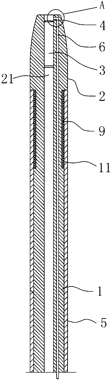
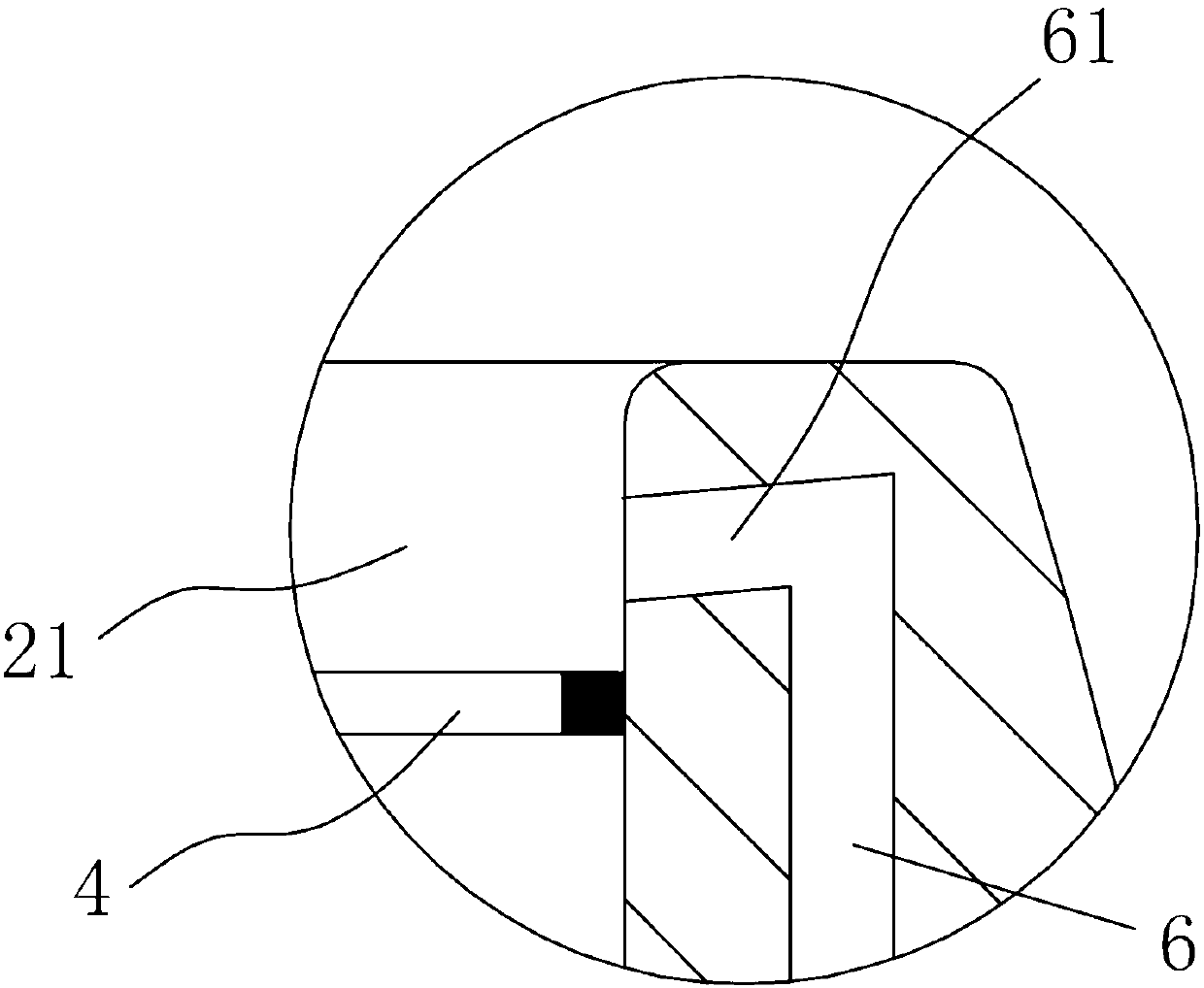
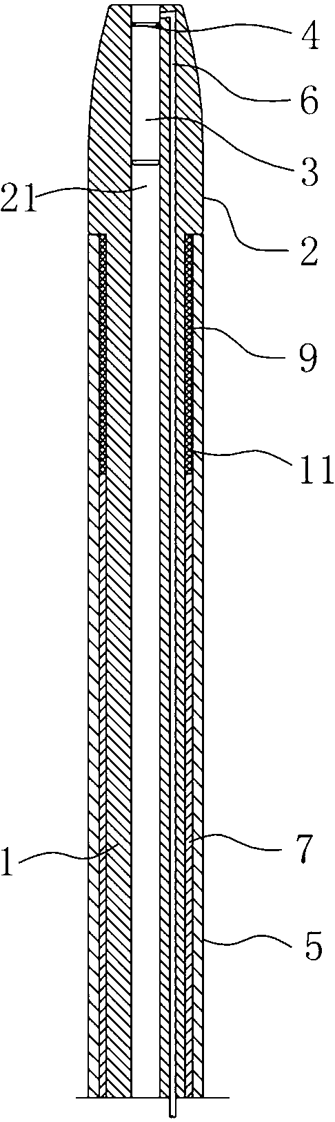
[0015] as attached figure 1 , attached figure 2 The visible stent releaser shown includes a guide tube 1 , a guide head 2 , an operation tube 5 and a cleaning tube 6 . The guide tube 1 has a soft tube body and can be inserted into the esophagus of a human body. The guide head 2 is arranged at the front end of the guide tube 1, and an installation hole 21 which axially penetrates the guide head 2 and communicates with the hollow part of the guide tube 1 is provided inside, and a camera is installed in the installation hole 21. The front end of the device 3 and the imaging device 3 is equipped with an illuminating light source 4 , and the imaging device 3 and the illuminating light source 4 are electrically connected to an external imaging device through the hollow part of the guiding tube 1 . With the help of the camera device 3, the doctor can directly observe the lesion to realize a visualized treatment system, which can improve the accuracy of the treatment and reduce the...


PUM


Abstract

The invention discloses a visual support releaser, and belongs to the technical field of medical equipment. The visual support releaser comprises a guiding tube, a guiding head and an operation head, wherein an installing hole is formed inside the guiding head, a photographic device is installed inside the installing hole, a lighting source is installed at the front end of the photographic device, a groove for accommodating a support is formed in the outer side wall of the guiding tube, and the visual support releaser further comprises a washing tube for washing the photographic device. The visual support releaser is simple in structure and convenient to operate. A doctor can directly observe a focus with the help of the photographic device, a visual treatment system is achieved, treatment accuracy can be improved, and surgical time is shortened. In addition, a radial device does not need to be used in the process of surgery, and the occurrence that the doctor is radiated by the radial device for a long time can be avoided.

Description

technical field [0001] The invention relates to a visual bracket releaser, which belongs to the technical field of medical instruments. Background technique [0002] Due to the unhealthy diet of modern people, various esophagus diseases are caused. For the narrowing of esophageal lesions, the common treatment method is to use stents to open the stenosis of esophageal lesions. The existing esophageal stent is mainly composed of several catheters and a guide head. Several catheters are nested together in sequence, and a cavity for placing the stent is arranged in the catheter. When the catheter reaches the lesion under the guidance of the guide head, The doctor operates the outermost catheter to retreat, so that the stent loses its restraint and opens, and the esophagus is stretched apart. However, the existing esophageal stents have a shortcoming, that is, they cannot be visualized, and medical staff need to use ultrasound guidance or X-rays to determine the position of the ...

Claims


Application Information

Patent Timeline
Patent Type & Authority Applications(China)
IPC IPC(8): A61F2/95
Inventor 郭爱军李志荣赖春来
Owner USHARE MEDICAL INC
Why Eureka
Try Eureka