A parallel electroluminescent wire

A technology of electroluminescent wires and luminous wires, which is applied in the direction of electroluminescent light sources, electric light sources, light sources, etc., and can solve problems such as complex lines and costs

Inactive Publication Date: 2015-08-26
SHANGHAI KERUN PHOSPHOR TECH
View PDF4 Cites 1 Cited by
  • Summary
  • Abstract
  • Description
  • Claims
  • Application Information

AI Technical Summary

Problems solved by technology

When multiple luminous wires are used in series, the voltage, frequency, and current will change significantly. When multiple luminous wires are used in parallel, the long-distance wire connection will cause complicated wiring and cost

Method used


Image

  • A parallel electroluminescent wire
  • A parallel electroluminescent wire
  • A parallel electroluminescent wire

Examples


Embodiment

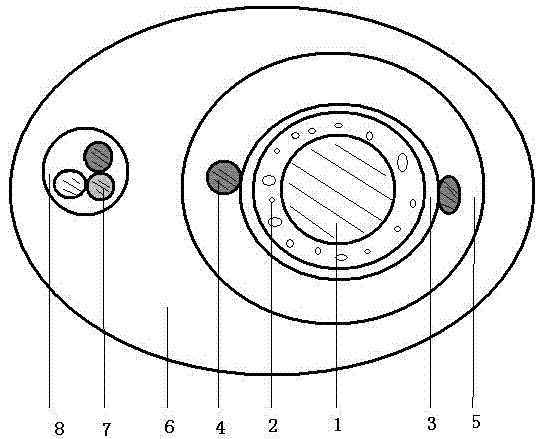
[0045] Preparation of luminous wire: 0.3 mm copper wire is used as the core wire electrode, the surface is coated with luminescent powder layer, the outer conductive layer is made of ITO material, the outer electrode is made of 0.1 mm silver-plated copper wire, and the transparent protective layer is made of PVC plastic.

[0046] The insulated metal wire is made of 0.1mm copper wire, and its surface is coated with an enamelled insulating layer. The surfaces of the three wires are red, blue and green. Three insulated metal wires are twisted into a cable and wrapped in PVC.

[0047] Insulated metal wires parallel to the luminous wires are wrapped in a layer of colored transparent plastic.

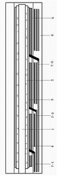
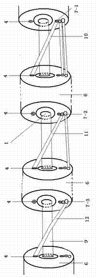
[0048] The luminous wires are cut into 200 meters each, a total of three, 600 meters in total, their core wire electrodes are connected in series in sequence, and the outer electrodes of the three sections of luminous wires are respectively connected to the red, blue and green insulated metal...


PUM


Abstract

A parallel-connection electroluminescent wire comprises a luminescent wire, a plurality of insulated metal electric wires, a colored transparent plastic layer and a driver. The parallel-connection electroluminescent wire is characterized in that the luminescent wire comprises a core wire electrode, a luminescent layer, an outer conducting layer, an outer electrode and a transparent protecting layer, and the driver comprises a driver core wire electrode output end and a driver outer electrode output end. When the parallel-connection electroluminescent wire is used, the driver core wire electrode output end is connected with the core wire electrode of the luminescent wire, the driver outer electrode output end is connected with the insulated metal electric wires in parallel, and the insulated metal electric wires are then connected with the outer electrode of the luminescent wire one by one in a sectional mode.

Description

technical field [0001] The invention belongs to the technical field of electroluminescent devices application. Background technique [0002] Existing electroluminescent devices rely on electrical energy conversion to produce light, and their work is basically divided into two parts: light-emitting devices and electronic drive devices. Their close integration is a necessary condition for the application of the overall device. The main devices of the existing AC powder electroluminescence line technology, the luminescence is generated under high field, so their use is usually accompanied by a driver. The electroluminescent line in the prior art usually has a luminous length of 100 meters. Even if the power of the driver is increased by 3-5 times, the length of the luminous line can only be increased to 200 meters. Increasing the length of the luminous line will make the driver, The luminous line generates heat, and at the same time, the brightness of the first and last ends o...

Claims


Application Information

Patent Timeline
Patent Type & Authority Patents(China)
IPC IPC(8): H05B33/26
Inventor 郑岩耿树范史陈峰许景琦郑林轩
Owner SHANGHAI KERUN PHOSPHOR TECH
Why Eureka
Try Eureka