
Method for broadcasting IP multicast signal by using optical splitter

An IP multicast and optical splitter technology, which is applied in the branch office to provide special service devices, data exchange details, etc., can solve problems such as not suitable for some services in the broadcasting and television system, and reduce the burden of operation and maintenance, with significant benefits and practicality strong effect

Active Publication Date: 2013-08-28
GUANGXI RADIO & TV NETWORK
View PDF2 Cites 3 Cited by
  • Summary
  • Abstract
  • Description
  • Claims
  • Application Information

AI Technical Summary

Problems solved by technology

[0007] The purpose of the present invention is to provide a method for an optical splitter to broadcast IP multicast signals, realize the transmission that can only be completed by a two-way network in a one-way transmission mode, and overcome the defect that the existing two-way network function is not suitable for some services of the radio and television system

Method used


Image

  • Method for broadcasting IP multicast signal by using optical splitter
  • Method for broadcasting IP multicast signal by using optical splitter
  • Method for broadcasting IP multicast signal by using optical splitter

Examples


Embodiment Construction

[0024] The technical solution of the present invention will be further described in detail according to the drawings and examples below.

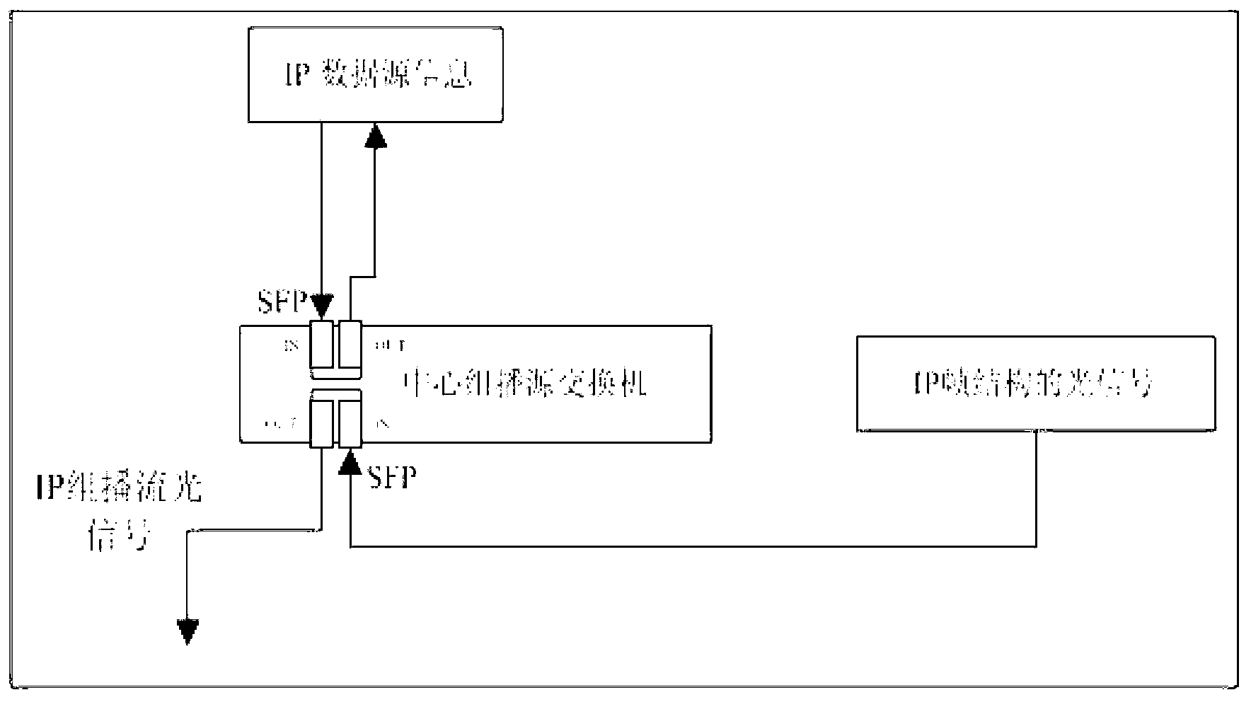
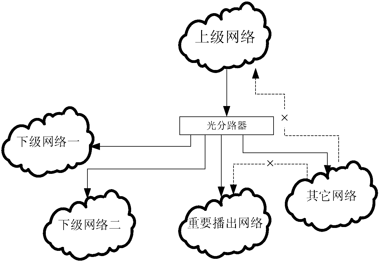
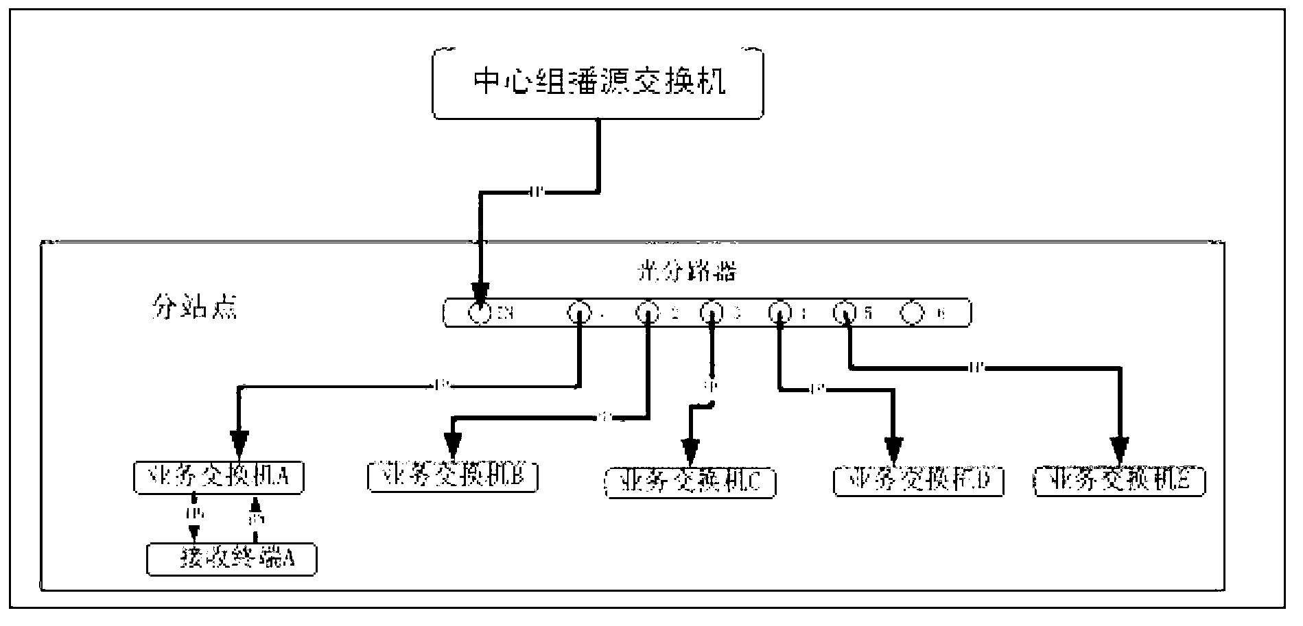
[0025] Such as Figure 1-Figure 3 As shown, the networking structure is that the central node sets up a central multicast source switch, and only one single-fiber IP multicast signal is output from the SFP module, which is connected to the IN port of the 6-way optical splitter, and the optical splitter splits The 5-way single-fiber IP multicast optical signal is connected to the IN port of the SFP module of the lower-level service switches A, B, C, D, and E, and the IN port of the service switch SFP completes the interface negotiation with the SFP OUT port of the central multicast source switch , the receiving terminal A is connected to the service switch A through a pair of single-mode optical fibers.

[0026] The method for broadcasting an IP multicast signal by an optical splitter of the present invention comprises the following steps: ...


PUM


Abstract

The invention discloses a method for broadcasting an IP multicast signal by using an optical splitter. The method comprises the following steps: (1) arranging a central multicast source switch on a central node, configuring a multicast source address, and transmitting the received superior IP data source information in the form of IP multicast stream; (2) forcibly activating the transmitting port of a SPF of the central multicast source switch, and inputting an IP multicast stream optical signal into the IN port of the optical splitter; (3) splitting an input IP multicast stream optical signal into different paths of output ports, and accessing the SFP module receiving port of an inferior service switch; and (4) replacing an IGMP querier of the central multicast source switch by the generated IGMP querier of the inferior service switch, and broadcasting the IP data source information to the inferior service switch. The method has the advantages of simple networking structure, scheduling flexibility, high stability and security, high practicability and suitability for being expanded and applied to metropoliatan area single-direction IP data networks.

Description

technical field [0001] The invention relates to a method for realizing a two-way data transmission mode by using one-way broadcast, in particular to a method for an optical splitter to broadcast an IP multicast signal. Background technique [0002] The radio and television network system has become an important news media and an important tool for the people to obtain knowledge, culture and entertainment. It is one of the national information infrastructures with the highest household registration rate. Its characteristics determine that its own network transmission must be safe and secure. The operation and maintenance must have its particularity and sensitivity. [0003] With the improvement of the integration of IP equipment, the increase of bandwidth, and the diversification of transmission equipment support, digital TV transmission IP brings highly intensive equipment, high concentration of information, and flexible business scheduling. It is a trend in the development...

Claims


Application Information

Patent Timeline
IPC IPC(8): H04L12/18
Inventor 赵冠臣张伟华吴润宗徐洪亮朱莹德杨京蔡坤于浩高欣谈毅谭俊光刘荣毅刘志东王沛
Owner GUANGXI RADIO & TV NETWORK
Learn More