
Feed and detection method of LED luminous energy and illuminating system

A technology for lighting systems and LED lamps, which can be used in the testing of optical performance, lamp testing, etc., can solve problems such as power waste and light pollution of LED lamps and lanterns

Inactive Publication Date: 2013-08-28
深圳莱特光电股份有限公司
View PDF6 Cites 12 Cited by
  • Summary
  • Abstract
  • Description
  • Claims
  • Application Information

AI Technical Summary

Problems solved by technology

[0004] The invention provides a LED light energy feeding and detection lighting system, which is used to solve the problems of power waste and light pollution in the aging process of LED lamps, and at the same time realize the whole process monitoring and recording of the aging process of LED lamps, and then achieve the purpose of accurate detection
[0005] The invention provides a control and analysis system for feeding and detecting LED light energy, which is used to solve the problems of electric energy waste and light pollution in the aging process of LED lamps, and at the same time realize the whole process of monitoring and recording the aging process of LED lamps, and then achieve accurate detection. Purpose
[0006] The invention provides a method for feeding and detecting LED light energy, which is used to solve the problems of electric energy waste and light pollution in the aging process of LED lamps, and at the same time realize the whole process monitoring and recording of the aging process of LED lamps, thereby achieving the purpose of accurate detection

Method used


Image

  • Feed and detection method of LED luminous energy and illuminating system
  • Feed and detection method of LED luminous energy and illuminating system
  • Feed and detection method of LED luminous energy and illuminating system

Examples


Embodiment Construction

[0057] In order to make the objectives, technical solutions and advantages of the present invention clearer, the present invention will be further described in detail below with reference to the accompanying drawings and embodiments. It should be understood that the specific embodiments described herein are only used to explain the present invention, but not to limit the present invention.

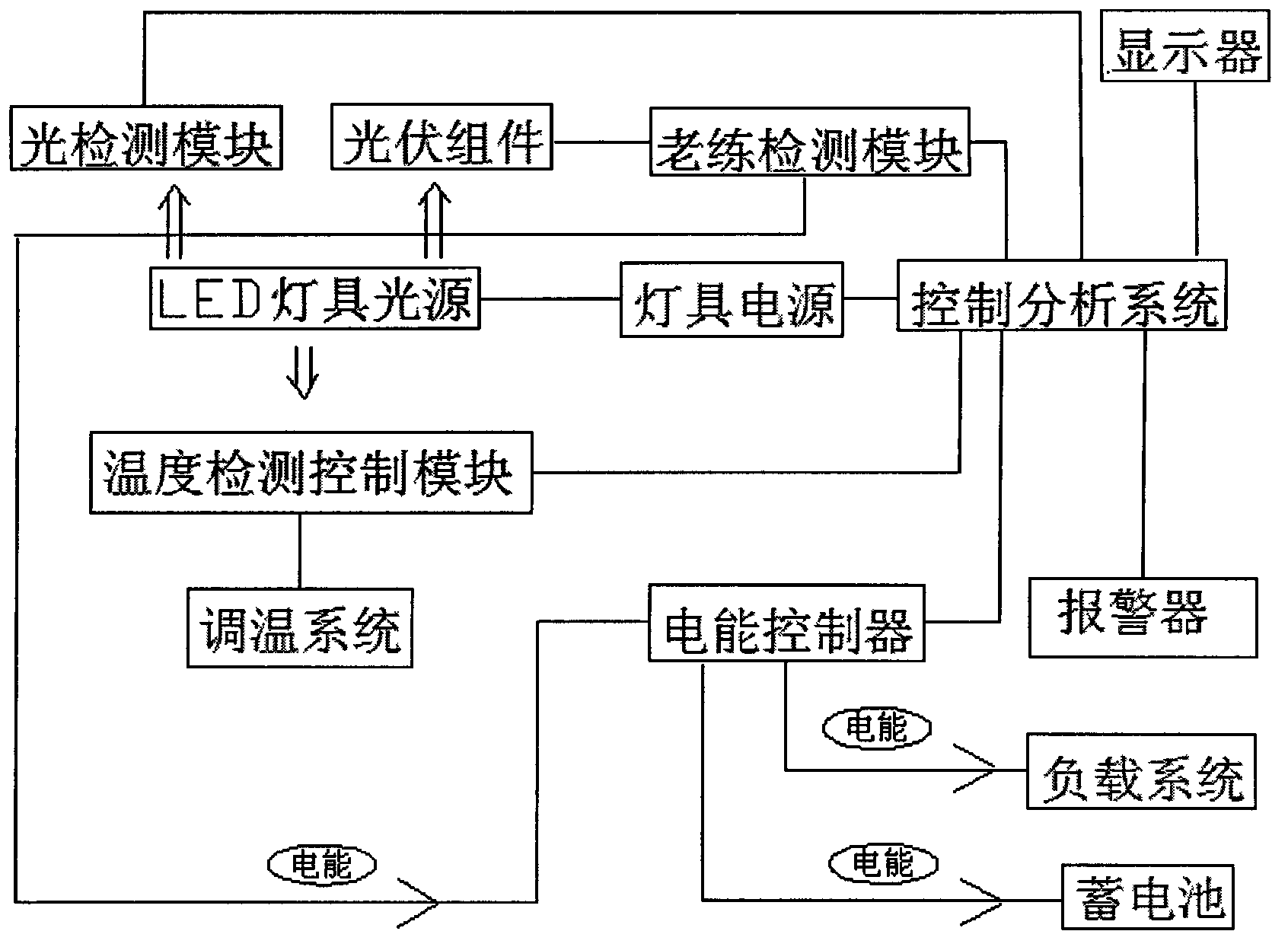
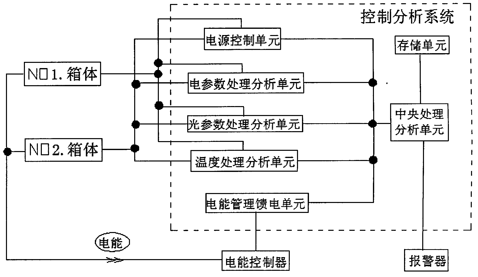
[0058] The present invention proposes a functional module diagram of an LED light energy feeding and detection lighting system. figure 1 and see figure 2 .

[0059]The light source of the LED lamp is connected to the power supply of the lamp. The aging detection module is connected with the photovoltaic module, and is used to obtain the electrical parameter information output by the photovoltaic module, transmit the electrical parameter information to the control analysis system, and transmit the electric energy to the electric energy controller. The power controller is used to control...


PUM


Abstract

The invention provides a feed and detection method of LED luminous energy and an illuminating system, and relates to the technology of an LED illuminating device and the detection technology of the LED illuminating device, and the photovoltaic energy-saving technology. The electric energy in the ageing process of an LED lamp is recycled, whole-process monitoring record of the ageing process of the LED lamp is achieved, and then the purpose of accuracy detection is achieved. According to the technical scheme, the luminous energy of a light source of the LED lamp is obtained through a photovoltaic module, and the luminous energy is converted into electric energy; electrical parameter information is obtained from the photovoltaic module through an ageing detection module, and the electric energy is conveyed to a storage battery and a load through an electric energy controller; temperature of a detection box where the LED lamp is located is detected, temperature parameters are obtained, temperature information and electrical parameter information are transmitted to a control analysis system and are analyzed and processed by the control analysis system, and data which can continuously record and monitor the ageing process of the LED lamp are generated. The control analysis system conducts summarizing, association, analyzing treatment and recording storage on the electrical parameter information and the temperature parameter information.

Description

technical field [0001] The invention relates to an LED lighting device and its detection technology, as well as a photovoltaic energy-saving technology. Background technique [0002] Photovoltaic power generation technology is a trend of clean energy utilization in the future. The photovoltaic power generation system is mainly composed of solar cells (photovoltaic modules), electric energy controllers, battery packs, etc. The input end of the electric energy controller is connected to the solar panel, and the output end is connected to the battery And the load, the charge and discharge of the battery is controlled by the electric energy controller. If the photovoltaic power generation system is connected to the grid, a grid-connected inverter needs to be transferred. [0003] During the assembly and production process of LED luminaires, they need to be subjected to sophistication testing. Take the aging test of street lamps as an example. Before leaving the factory, each l...

Claims


Application Information

Patent Timeline
IPC IPC(8): G01R31/44G01M11/02
Inventor 冯海涛蔡德晟
Owner 深圳莱特光电股份有限公司
Learn More