
Device and method for measurement of internal temperature of solid metal

A technology of internal temperature and measuring devices, applied in measuring devices, thermometers, measuring heat, etc., can solve the problems of not being able to measure the internal temperature of solid metals, and achieve the effects of easy installation and extraction, convenient installation, and high measurement accuracy

Inactive Publication Date: 2013-08-28
NUCLEAR POWER INSTITUTE OF CHINA
View PDF1 Cites 7 Cited by
  • Summary
  • Abstract
  • Description
  • Claims
  • Application Information

AI Technical Summary

Problems solved by technology

[0005] The purpose of the present invention is to overcome the deficiency that the existing metal temperature measurement technology cannot measure the internal temperature of solid metal, and to provide a solid metal internal temperature measurement device

Method used


Image

  • Device and method for measurement of internal temperature of solid metal
  • Device and method for measurement of internal temperature of solid metal
  • Device and method for measurement of internal temperature of solid metal

Examples


Embodiment 1

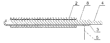
[0046] Such as figure 1 As shown, the solid metal internal temperature measuring device includes an insulating sleeve 2 and an armored thermocouple 3. The insulating sleeve 2 is sleeved on the armored thermocouple 3 and at least exposes the temperature measuring end of the armored thermocouple 3.

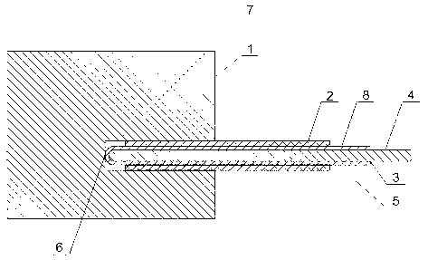
[0047] Such as figure 2 As shown, in this embodiment, when in use, it is directly inserted into the blind hole 7 on the metal 1 to be tested, so that the temperature measuring end of the armored thermocouple 3 is in contact with the bottom of the blind hole 7 .

[0048] If only armored thermocouples are used, the following problems will occur:

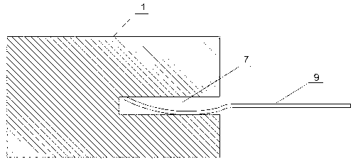
[0049] Such as image 3 As shown, when the flexible armored thermocouple 9 is selected, after it is inserted into the blind hole 7, it is difficult to ensure that the part inserted into the blind hole 7 does not bend. The hole wall of the blind hole 7 is in contact, and the temperature measuring end of the flexible armored thermocouple 9...

Embodiment 2

[0053] Such as figure 1 and figure 2 As shown, the present embodiment is based on Embodiment 1, and the armored thermocouple 3 includes a thermocouple wire 4 and an armored shell 8, and the armored shell 8 wraps the thermocouple wire 4, and the two ends of the armored shell 8 are both Exposed from the insulating sleeve 2 , it also includes a grounding wire 5 connected to the end of the armored shell 8 away from the temperature measuring end of the armored thermocouple 3 . When the metal 1 to be tested is charged, it will cause great electromagnetic interference to the armored thermocouple 3 that penetrates into the metal. By grounding the armored shell 8, effective shielding of electromagnetic interference can be achieved, so that this embodiment has a relatively Strong anti-interference ability. In addition, due to the existence of the insulating sleeve 2, the metal under test 1 can be prevented from being grounded after the armored shell 8 is grounded.

Embodiment 3

[0055] Such as figure 1 and figure 2 Shown, present embodiment is on the basis of above-mentioned embodiment, and the diameter of described armored thermocouple 3 is 5 * 10 -4 ~1.5×10 -3 m. Under the condition that the diameter of the blind hole 7 should be as small as possible, the selection of the armored thermocouple 3 with the above diameter can realize the internal temperature of the metal 1 to be tested without affecting the structure, internal temperature distribution and mechanical properties of the metal 1 to be tested. Measurement.


PUM

PropertyMeasurementUnit
diameteraaaaaaaaaa
thicknessaaaaaaaaaa

Abstract

The invention discloses a device for measurement of internal temperature of solid metal. The device for measurement of the internal temperature of the solid metal comprises an insulating sleeve and a sheathed thermocouple, wherein the insulating sleeve is sleeved on the sheathed thermocouple, and enables at least the temperature measuring end of the sheathed thermocouple to be exposed. The invention further discloses a method for measurement of the internal temperature of the solid metal. The method for measurement of the internal temperature of the solid metal comprises the following steps of (1) drilling a blind hole towards a point to be measured from the position, closest to the point to be measured, of the surface of metal to be measured, wherein the point to be measured is arranged at the bottom of the blind hole, (2) installing the device for measurement of the internal temperature of the solid metal into the blind hole, and enabling the temperature measuring end of the sheathed thermocouple to make contact with the point to be measured, (3) welding the temperature measuring end of the sheathed thermocouple and the point to be measured together through pulse welding, and (4) carrying out temperature measurement. The device for measurement of the internal temperature of the solid metal and the method for measurement of the internal temperature of the solid metal have the advantages of overcoming the defect that the internal temperature of the solid metal can not be measured through an existing metal temperature measuring technology.

Description

technical field [0001] The invention relates to the field of nuclear industry, in particular to a device and method for measuring the internal temperature of solid metal. Background technique [0002] Since humans began to use nuclear energy, there have been many serious nuclear leakage accidents around the world, such as the Three Mile Island nuclear leakage accident in the United States, the Chernobyl nuclear leakage accident in the former Soviet Union, and the Fukushima nuclear leakage accident in Japan. Through the analysis of the development and treatment process of the above-mentioned nuclear leakage accident, it can be found that keeping the core melt in the pressure vessel and ensuring the integrity of the reactor pressure vessel can greatly alleviate the further development and deterioration of the severe accident. [0003] Now, there is a relatively complete reactor melt retention strategy, and the key points that affect the success of the reactor melt retention st...

Claims


Application Information

Patent Timeline
Patent Type & Authority Applications(China)
IPC IPC(8): G01K7/02G01K1/08G01K1/14
Inventor 张震熊万玉王雄李朋洲卓文彬张兴武韩群霞
Owner NUCLEAR POWER INSTITUTE OF CHINA
Learn More