Shifting to extended-range new energy vehicles with safe and reliable braking

A new energy vehicle and extended-range technology, applied in the field of vehicles, can solve problems such as reducing energy conversion rate, accelerating battery, and motor heating, so as to avoid energy loss, maintain service life, and reduce research and development costs.

Active Publication Date: 2017-11-21
南京海芸博信息科技发展有限公司
View PDF2 Cites 0 Cited by
  • Summary
  • Abstract
  • Description
  • Claims
  • Application Information

AI Technical Summary

Problems solved by technology

[0003] However, the structure of new energy vehicles is different from that of fuel vehicles, so that new energy vehicles have no force to use to achieve power-assisted braking.
Chinese patent 200910209815.X discloses an electric power-assisted brake assist system for electric vehicles. In this system, the battery of the electric vehicle provides working power for the vacuum pump, and the vacuum pump provides braking power through the vacuum booster. Although this method realizes the power-assisted braking of electric vehicles, However, at the cost of consuming battery power, the driving range of electric vehicles is further shortened.
Conversely speaking, although the shock absorber with high hardness will reduce the possibility of the vehicle rolling over, it will be extremely uncomfortable due to the severe bumps of the vehicle due to the excessive hardness.
Chinese patent 200910143765.X discloses a car with an anti-rollover system and an anti-rollover system. The system moves the center of gravity of the car to the inside by raising the height of the car body on the outer side of the turn and lowering the height of the car body on the inner side of the turn. , so as to effectively prevent the car from rolling over, but the active hydraulic cylinder and the plunger of the passive hydraulic cylinder of this anti-rollover system are in a fixed position when the vehicle is going straight, thereby fixing the distance between the chassis of the car body and the axle, making the shock absorber The device loses its shock absorbing function
However, in the climbing or accelerating section, it is still necessary to increase the current output to maintain the vehicle's driving speed. During this process, the peak current may even be reached, thereby accelerating the release of battery power. At the same time, the large current will also cause the motor to heat up. Further increase the internal resistance of the motor, reduce the energy conversion efficiency, and even shorten the service life of the electric vehicle power system because the battery and the motor are often in a high-current working state
And it is necessary to convert the chemical energy of the fuel into the kinetic energy of the engine first, and then convert the kinetic energy into electrical energy, which increases the intermediate link of energy conversion and reduces the energy conversion rate

Method used


Image

  • Shifting to extended-range new energy vehicles with safe and reliable braking
  • Shifting to extended-range new energy vehicles with safe and reliable braking
  • Shifting to extended-range new energy vehicles with safe and reliable braking

Examples


Embodiment 1

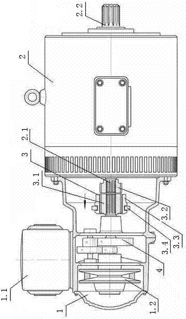
[0038] On the one hand, the present invention improves the power system of the new energy vehicle, specifically as figure 1As shown, the power output shaft of the continuously variable speed engine 1 is connected to the tooth clutch 3 through the speed reducer 4, and the tooth clutch 3 includes the active external tooth 3.1, the driven external tooth 3.2 and the clutch ring gear 3.3. Among them, the driven external gear 3.2 is installed on the input shaft of the motor, the active external gear 3.1 is installed on the reducer 4, the clutch ring gear 3.3 can mesh with the active external gear 3.1 and the driven external gear 3.2 at the same time, and the clutch ring gear 3.3 Connect the clutch shift fork 3.4, the clutch shift fork 3.4 drives the clutch ring gear 3.3 to move along the axial direction of the active external tooth 3.1 and the driven external tooth 3.2, to switch the transmission between the active external tooth 3.1 and the driven external tooth 3.2. In this way, t...

Embodiment 2

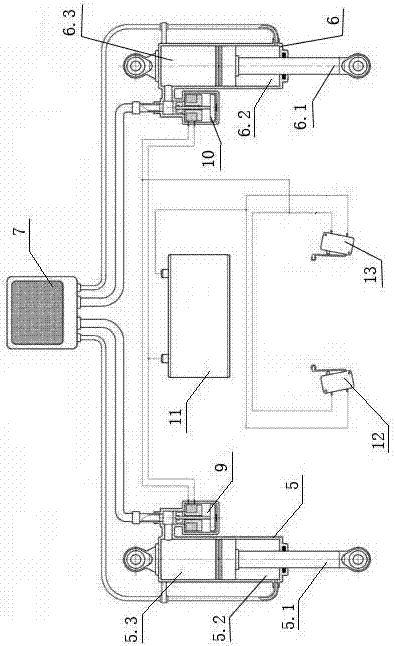
[0050] This embodiment is a modification of Embodiment 1: specifically as Figure 5 As shown, the working chambers 5.3 and 6.3 of the left cylinder 5 and the right cylinder 6 communicate with the same air filter 7 through the same pipeline, and the first electromagnetic valve 9 is arranged on the same pipeline, that is, the left cylinder 5 and the left cylinder are simultaneously controlled by the first electromagnetic valve 9. The working state of the right cylinder 6. When the vehicle turns, the left cylinder 5 and the right cylinder 6 are "locked" and cannot move freely, and all the others are the same as in the first embodiment.

Embodiment 3

[0052] This embodiment is another modification of the first embodiment: the first button 12 only controls the power on and off of the first solenoid valve 9 ; the second button 13 only controls the power on and off of the second solenoid valve 10 . When the vehicle turned to the left, the second button 13 was pressed, only the second electromagnetic valve 10 was energized, and the right cylinder 6 was closed to support the vehicle body and the axle, preventing the right side of the vehicle body from pressing down and turning right. When the vehicle turns to the right, press the first button 12, only the first electromagnetic valve 9 is energized, and the left cylinder 5 is closed to support the car body and the axle, preventing the left side of the car body from being pressed down and turning left. All the other are the same as embodiment one.

[0053] The electromagnetic valve in the above embodiment can also be an electric control valve or an on-off valve with other structur...


PUM


Abstract

The invention discloses a range-extended new energy vehicle with safe steering and reliable braking, which belongs to the technical field of vehicles, and includes a vehicle body, an axle, a brake arm, a brake master cylinder and a steering wheel, and a drive axle is installed on the vehicle body. The motor is characterized in that: it also includes a stepless speed regulation engine, a speed reducer, a brake main pump, a brake disc, a brake pressure plate, a booster pump and a brake cylinder; the power output shaft of the stepless speed regulation engine is sequentially reduced The input shaft of the motor is connected with the gear and the tooth clutch; a steering balance device is added between the car body and the axle, and a power-assisted braking device is installed on the car body. This kind of new energy vehicle can effectively increase its mileage by reducing the weight of the vehicle, slowing down the release speed of electric energy, and picking up inertial energy to assist braking. Rollover will not occur, and the shock absorbing effect will not be affected when driving straight, which improves driving safety.

Description

technical field [0001] The invention belongs to the technical field of vehicles, and in particular relates to an extended-range new energy vehicle with safe steering and reliable braking. Background technique [0002] In recent years, with the continuous improvement of people's quality of life, automobiles have gradually entered the families of ordinary people and become a means of transportation for the majority of people. At the same time, more and more gas emissions have polluted the environment. Under the background of the environmental protection department advocating green environmental protection, new energy vehicles with various uses have emerged as the times require. Most of the current new energy vehicles use the electric energy stored in the battery as the power source. In practical application, the most prominent problems are short driving range and difficult braking. As we all know, in order to realize the timely braking of vehicles, the brake parts need to mee...

Claims


Application Information

Patent Timeline
Patent Type & Authority Patents(China)
IPC IPC(8): B60T11/16
Inventor 任祥意
Owner 南京海芸博信息科技发展有限公司
Why Eureka
Try Eureka