
Clamping device and clamping and positioning method thereof

A technology of clamping device and pressing screw, applied in the direction of positioning device, clamping, support, etc., can solve the problems of affecting the product quality of the workpiece to be positioned, the surface of the workpiece is crushed, and the auxiliary positioning time is long, so as to improve the workpiece quality. The effect of positioning efficiency, improving clamping efficiency, and quick and convenient positioning adjustment

Inactive Publication Date: 2013-08-28
FUZHEN TECH RES ANHUI
View PDF8 Cites 15 Cited by
  • Summary
  • Abstract
  • Description
  • Claims
  • Application Information

AI Technical Summary

Problems solved by technology

Due to the need to constantly adjust the height of the jack and the pressing surface, it takes a long time for auxiliary positioning and the work efficiency is low; and when the jack is higher than the pressing surface of the workpiece, the front end of the pressing plate pressed on the pressing surface contacts and compresses the workpiece line , when the jack is lower than the pressing surface of the workpiece, the rear end of the pressing plate pressed on the pressing surface is in contact with the workpiece line; only when the jack is completely equal to the pressing surface of the workpiece, the pressing plate is in contact with the workpiece surface; The pressure plate is in line contact with the workpiece, which will cause crushing on the surface of the processed workpiece; affect the product quality of the positioned workpiece

Method used


Image

  • Clamping device and clamping and positioning method thereof
  • Clamping device and clamping and positioning method thereof
  • Clamping device and clamping and positioning method thereof

Examples


Embodiment Construction

[0031] The specific implementation manner of the present invention will be described in further detail below by describing the best embodiment with reference to the accompanying drawings.

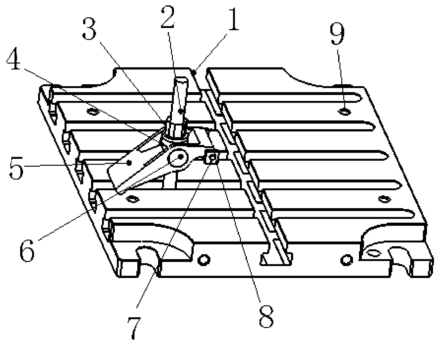
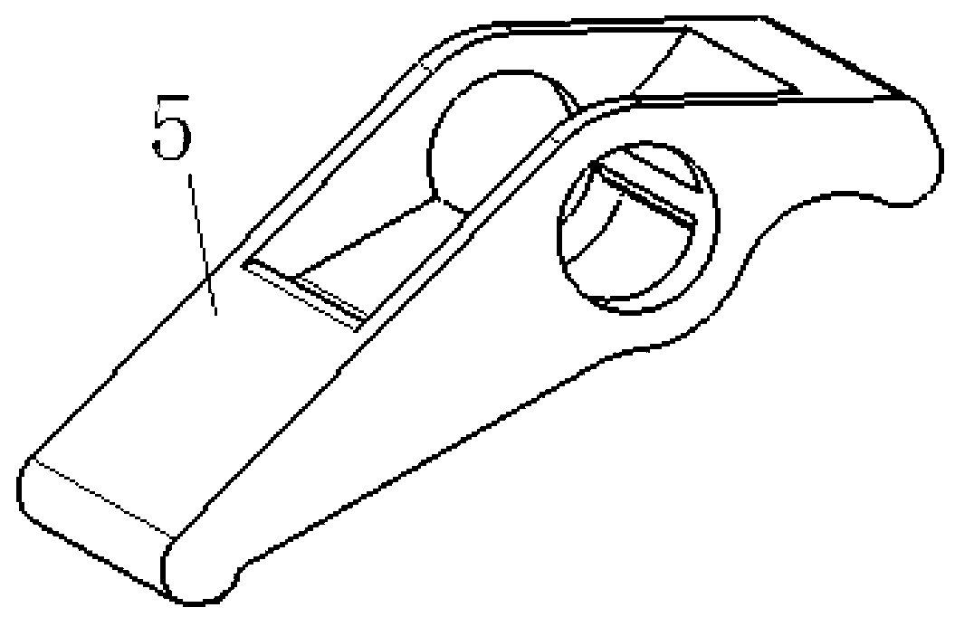
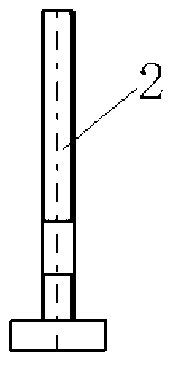
[0032] Such as Figure 1 to Figure 7 As shown, the clamping device is used for the positioning of workpieces such as die forging inserts and steel plates, and includes an auxiliary workbench 1 and an arc-shaped pressure plate 5. A compression screw 2 is provided on the auxiliary workbench 1. A pressing plate rotating shaft 6 is provided; the middle part of the pressing plate rotating shaft 6 passes through the pressing screw 2, one end of the arc-shaped pressing plate 5 is in contact with the auxiliary workbench 1, and the other end of the arc-shaped pressing plate 5 is provided with a pressing plate 8 for pressing the workpiece to be positioned. The pressing plate 8 is pressed against the surface of the workpiece;

[0033] The nut washer 4 adapted to the lock nut 3 is arranged on the pres...


PUM


Abstract

The invention discloses a clamping device and a clamping and positioning method thereof. The clamping device is used for positioning workpieces of mold forging piece inserts, steel plates and the like and comprises an auxiliary working table and an arc-shaped pressing plate. A pressing screw is arranged on the auxiliary working table, a pressing plate rotation shaft is arranged on the arc-shaped pressing plate, the pressing screw penetrates the middle of the pressing plate rotation shaft, one end of the arc-shaped pressing plate contacts with the auxiliary working table, a pressing plate for pressing workpieces to be positioned is arranged at the other end of the arc-shaped pressing plate, and a locking nut matched with the pressing screw is installed on the pressing plate rotation shaft in a pressing mode. According to the clamping and positioning method, positioning of the workpieces is achieved through a clamping and positioning device. The clamping device and the clamping and positioning method of the clamping device can improve workpiece positioning efficiency, further improve working efficiency, and meanwhile can guarantee surface quality of products.

Description

technical field [0001] The invention relates to a clamping device and a clamping and positioning method for pressing die forging inserts and steel plates on a machine tool. Background technique [0002] In the mold processing industry, almost every subsequent mold has mold forging inserts and / or steel plates that need to be processed on the machine tool, and forging inserts and steel plates need to be positioned and clamped on the machine tool when processing. The pressing device commonly used in the industry is an ordinary pressing plate pressing device at present. This pressing plate pressing device includes a pressing plate, a jack is arranged at the bottom of one end of the pressing plate, and the other end of the pressing plate is pressed against the workpiece surface by a pressing nut. [0003] This kind of pressing plate pressing device, in the process of pressing the workpiece, needs to adjust the jack according to the height of the pressing surface of the workpiece...

Claims


Application Information

Patent Timeline
Patent Type & Authority Applications(China)
IPC IPC(8): B23Q3/06
Inventor 汤金所
Owner FUZHEN TECH RES ANHUI
Learn More