Movable lift type surgical observing stool
A lifting and surgical technology, which is applied to other seating furniture, household appliances, chairs, etc., can solve the problems of large space occupation, inconvenient moving, inconvenient operation process, etc., and achieve low production cost, simple structure, and easy cleaning Sanitation or Storage Effects
- Summary
- Abstract
- Description
- Claims
- Application Information
AI Technical Summary
Problems solved by technology
Method used
Image
Examples
Embodiment 1
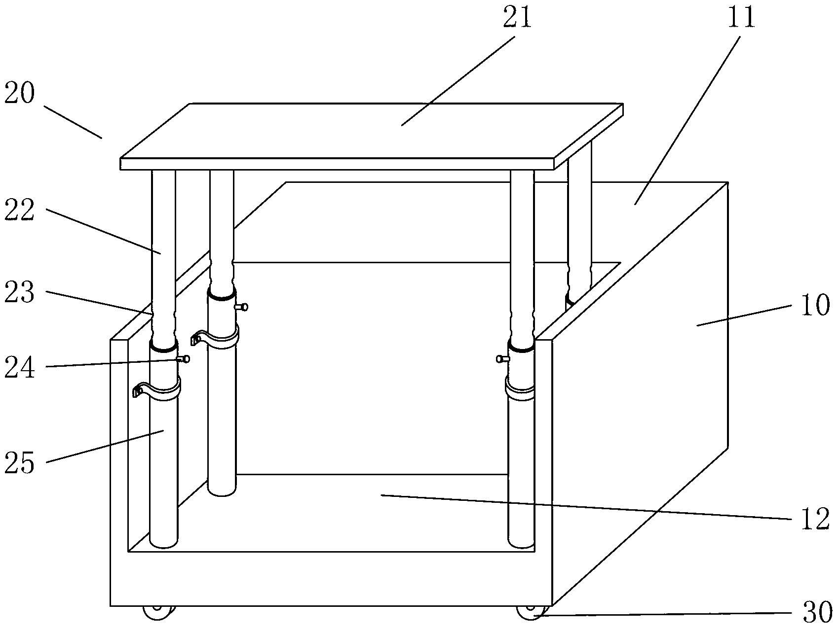
[0021] Embodiment 1, see figure 1 — figure 2 :
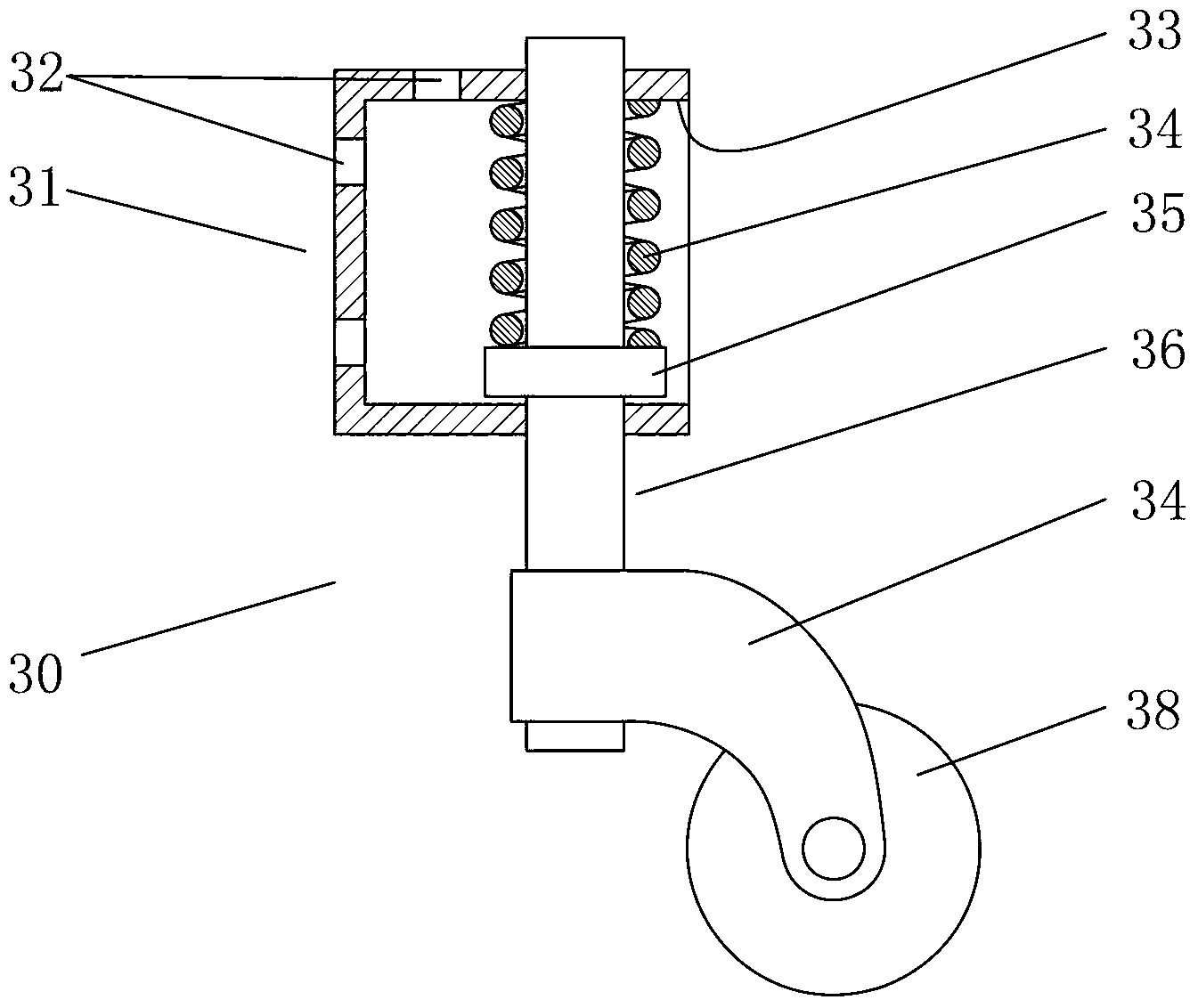
[0022] Mobile lifting type operation observation stool, the middle rear part of casing 10 is provided with the lifting device that controls lifting table 21 lifting, and the four corners of the bottom of casing 10 are provided with the roller 30 that can stretch up and down.
[0023] The specific structure of the above-mentioned lifting device is: the middle and rear part of the box body 10 is provided with more than three telescopic rods formed by the inner tube 22 being sleeved in the outer tube 25, the upper ends of all the telescopic rods are connected with the lifting platform 21, and the inner tube 22 is connected with the outer tube. Adjustment holes 23 are all provided on the 25, and the positions of the adjustment holes 23 different on the inner pipe 22 and the outer pipe 25 are inserted by the latch 24 to adjust the height of the elevating platform.
[0024] Above-mentioned telescoping link is by four, is located on...
Embodiment 2
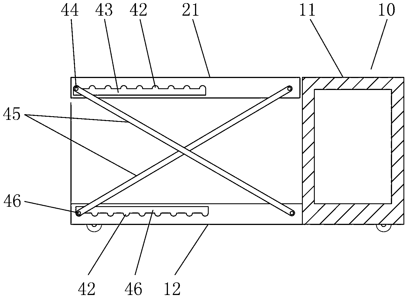
[0027] Embodiment 2, see figure 2 , image 3 , Figure 4 :
[0028] The structure of embodiment 2 is basically the same as that of embodiment 1, the difference is:
[0029] The specific structure of the above-mentioned lifting device is: two sets of four-linkage lifting mechanisms are arranged in the middle and rear part of the box body 10, and the two sides of the lower surface of the lifting table 21 and the upper surface of the inner bottom wall 12 of the middle and rear part of the box body 10 The height adjustment chute 43, 46 parallel to each other is correspondingly arranged on both sides, and the upper side of the chute 43 on the lifting platform 21 and the lower side of the chute 46 on the bottom wall 12 of the box body are correspondingly provided with a C-shaped chute communicating with the chute. Positioning grooves 42, 47, one end of two connecting rods 45 arranged crosswise on each side are hinged on the lifting platform 21 or the bottom wall 12 of the box bo...
Embodiment 3
[0030] Embodiment 3, see Figure 5 , figure 2 :
[0031] The structure of embodiment 3 is basically the same as that of embodiment 1, the difference is: the specific structure of the above-mentioned lifting device is: an electric lifting device (not shown in the specific structure diagram) is arranged in the middle and rear part of the box body 10, or at least There are more than one vertical jack (not shown in the specific structure diagram) or lifting hydraulic cylinder 53, the lower side of the jack or lifting hydraulic cylinder 53 is fixed on the box body 10, and the upper end is fixed on the bottom surface of the lifting table 21. The jack Lifting is manually driven, and the lifting hydraulic cylinder 53 is supplied by a pressure source and controlled by an electromagnetic reversing valve. When the lifting hydraulic cylinder 53 is set, for the stability of the lifting platform 21, guide rods can be set around the lifting platform 21. 51, a guide cylinder 52 is provided...
PUM
 Abstract
Description
Claims
Application Information
 - R&D
- Intellectual Property
- Life Sciences
- Materials
- Tech Scout
- Unparalleled Data Quality
- Higher Quality Content
- 60% Fewer Hallucinations
Browse by: Latest US Patents, China's latest patents, Technical Efficacy Thesaurus, Application Domain, Technology Topic, Popular Technical Reports.
© 2025 PatSnap. All rights reserved.Legal|Privacy policy|Modern Slavery Act Transparency Statement|Sitemap|About US| Contact US: help@patsnap.com


