
Thin film solar cell panel and preparation method of same

A technology of solar panels and solar cells, applied in circuits, photovoltaic power stations, photovoltaic power generation, etc., can solve the problem of not being able to directly process bendable solar cells, thin-film solar cells have not been well developed, and the degree of adaptability of different products Limitations and other issues, to achieve the effect of good insulation performance, good appearance, and improved light transmittance

Active Publication Date: 2013-08-21
NINGBO SANDI SOLARTECH CO LTD
View PDF7 Cites 14 Cited by
  • Summary
  • Abstract
  • Description
  • Claims
  • Application Information

AI Technical Summary

Problems solved by technology

[0005] Most polymer substrates do not have light transmission and high temperature resistance at the same time, that is, they cannot withstand The above process temperature, while the thickness of the glass substrate selected by the existing thin-film solar cell technology is generally greater than 3mm, which is not bendable, and cannot be directly used for processing and making bendable solar cells.
In addition, most of the existing thin-film solar cell manufacturing equipment and processes are built on flat substrates, such as flat float glass, which makes it very difficult to directly manufacture thin-film solar cells with a certain curvature
If thin-film solar cells are to be processed and manufactured by uniform coating on curved substrates, major changes to coating equipment and processes are required, which will not only greatly increase the cost, but also have different shapes due to different curved structure surfaces. and bending radians, resulting in great limitations in the adaptability of the equipment and process to different products
Based on the above reasons, the application of thin-film solar cells in the field of bendable products has not been well developed.

Method used


Image

  • Thin film solar cell panel and preparation method of same
  • Thin film solar cell panel and preparation method of same
  • Thin film solar cell panel and preparation method of same

Examples


Embodiment Construction

[0051] The present invention will be described in detail below in conjunction with the specific embodiments shown in the accompanying drawings, but these embodiments do not limit the present invention, those of ordinary skill in the art make structural, method, or functional changes based on these embodiments All are included in the scope of protection of the present invention.

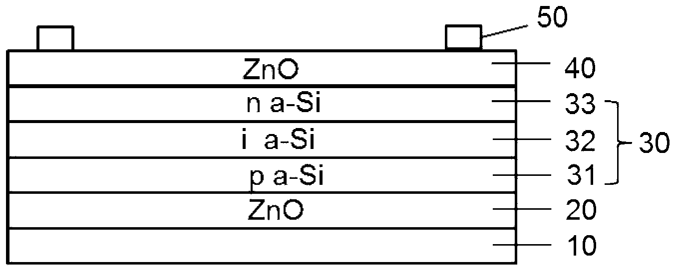
[0052] figure 1 It is a schematic diagram of a preferred embodiment of the thin film solar cell panel provided by the present invention. refer to figure 1 , the thin film solar cell panel includes a substrate 10, a first electrode 20 on the substrate, a photoelectric conversion layer 30 on the first electrode, a second electrode 40 on the photoelectric conversion layer 30, and Including the gate electrode 50 on the second electrode. The substrate 10 is an ultra-thin glass substrate, and the thickness of the ultra-thin glass substrate is 0.1-1mm. The ultra-thin glass substrate is bendable, and its m...


PUM


Abstract

The invention discloses a thin film solar cell panel and a preparation method of the thin film solar cell panel. The thin film solar cell panel comprises a substrate, a first electrode located on the substrate, a photoelectric conversion layer located on the first electrode, a second electrode located on the photoelectric conversion layer and a gate electrode arranged on the second electrode. The substrate is an extremely thin glass substrate with the thickness of 0.1-1mm, wherein the extremely thin glass substrate is bendable, the minimum bending radius of the extremely thin glass substrate is less than 10cm, and the first electrode is continuously arranged on the substrate in the forming process. The thin film solar cell panel and the preparation method of the thin film solar cell panel improve light-permeating performance of the thin film solar cell panel, ensure that the thin film solar cell panel can be conveniently used for manufacturing bent solar cell modules, improve preparation processes of the bendable think film solar cell panel, avoid increasing extra costs, and greatly increase universal applicability of equipment and the preparation method when the equipment and the preparation method are applied to the bendable thin film solar cell panel.

Description

technical field [0001] The invention relates to the field of solar photovoltaic products, in particular to a thin-film solar panel and a preparation method thereof. Background technique [0002] Thin-film solar cells have experienced a long development process from invention to large-scale commercialization. In 1976, the first amorphous silicon thin-film solar cell was successfully developed by Radio Corporation of America (RCA). Since the mid-1990s, with the continuous improvement of semiconductor manufacturing equipment and manufacturing technology, efficient stacking Silicon-based thin-film solar cells have achieved large-scale commercial production, and their light-absorbing materials have developed from the initial amorphous silicon homogeneous structure to a heterojunction structure composed of amorphous silicon, polycrystalline silicon and single crystal silicon. In addition to silicon-based thin-film solar cells, thin-film solar cells based on inorganic semiconducto...

Claims


Application Information

Patent Timeline
Patent Type & Authority Applications(China)
IPC IPC(8): H01L31/042H01L31/18H01L31/0445
CPCH01L31/03921H01L31/03926H01L31/0445Y02B10/10Y02E10/548H01L31/022425H01L31/022466H01L31/18H02S10/40H02S20/26Y02E10/50B60J7/043H01L31/1876H01L31/0463H01L31/0468
Inventor 杨立友
Owner NINGBO SANDI SOLARTECH CO LTD
Learn More