
Piston type engine crank connecting rod mechanism

A technology of crank connecting rod mechanism and piston engine, which is applied in the directions of engine components, machines/engines, pistons, etc., can solve the problem of affecting the structural movement stability of the crank connecting rod mechanism, increasing the contact area between the top surface of the piston and the combustion chamber, and affecting the combustion. Indoor gas mixing and combustion problems, to achieve the effect of reducing maintenance costs, reducing contact area, and helping in-cylinder combustion

Active Publication Date: 2013-08-21
重庆小康动力有限公司
View PDF6 Cites 3 Cited by
  • Summary
  • Abstract
  • Description
  • Claims
  • Application Information

AI Technical Summary

Problems solved by technology

The existing top surface of the piston and the circumferential side of the piston are often transitioned through smooth chamfering, which often causes the processing surface of the piston top surface to not match the processing surface of the combustion chamber surface at the lower end of the engine cylinder head, and the peripheral edges of the two will remain gap, which affects the mixing and combustion of gas in the combustion chamber, thereby affecting the output power of the engine; and the design of the chamfer structure will also increase the contact area between the top surface of the piston and the combustion chamber, making the stress distribution on the top surface of the piston uneven, thus Affects the kinematic stability of the overall structure of the crank linkage mechanism

Method used


Image

  • Piston type engine crank connecting rod mechanism
  • Piston type engine crank connecting rod mechanism
  • Piston type engine crank connecting rod mechanism

Examples


Embodiment Construction

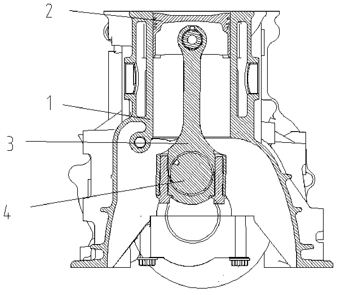
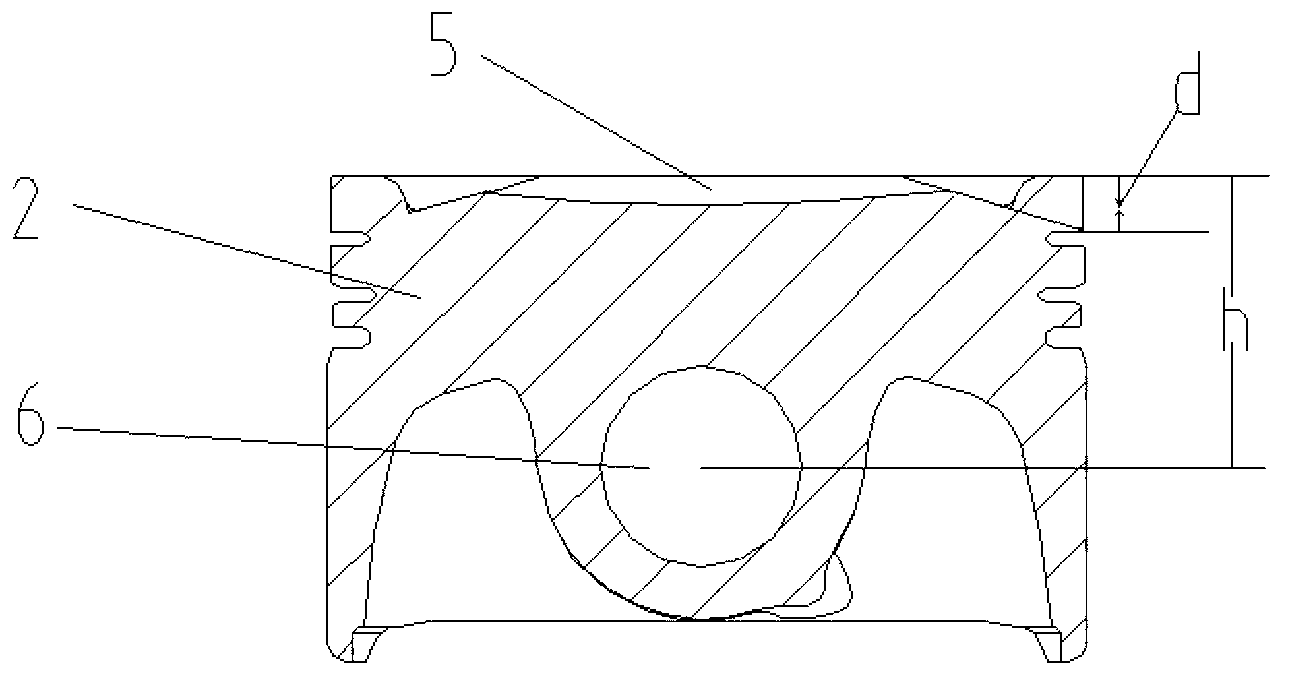
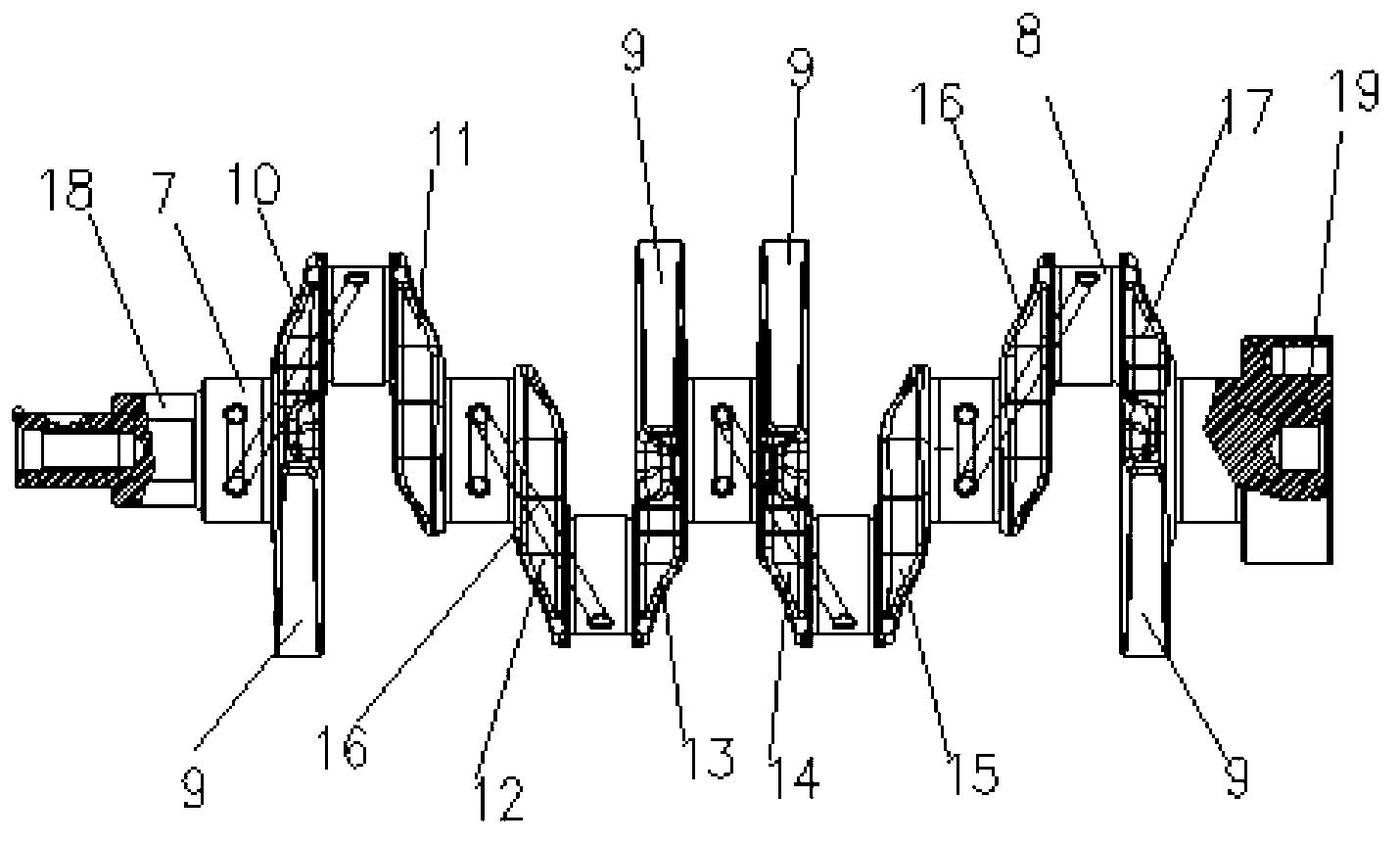
[0023] figure 1 It is a schematic diagram of the structure of the present invention, figure 2 is a schematic diagram of the piston structure, image 3 Schematic diagram of the crankshaft structure, Figure 4 It is a schematic diagram of the connecting rod structure, as shown in the figure: the piston engine crank connecting rod mechanism of this embodiment includes a cylinder 1, a piston 2, a connecting rod 3 and a crankshaft 4, and the top surface of the piston 2 is recessed inwardly and is provided with a bowl-shaped combustion chamber. Pit 5, the top surface of the piston and the piston circumferential side are flat-top structure transitions; the flat-top structure transition refers to the circumferential radial surface of the piston top surface from the upper edge of the combustion pit circumference to the circumferential side of the piston. The sharp edge structure of the corner, and the connection between the top surface of the piston and the side surface of the pisto...


PUM


Abstract

The invention discloses a piston type engine crank connecting rod mechanism which comprises an air cylinder, a piston, a connecting rod and a crankshaft. The top surface of the piston is concave inward and is provided with a bowl-shaped burning pit. The top surface of the piston and the side of the periphery of the piston are flat structure transition. A machined face of a combustor of an air cylinder cover is enabled to be matched with a machined face of the top surface of the piston, and therefore stability of quality of volume production is guaranteed. The top surface of the piston which is of a flat structure can be matched with the air cylinder cover to form a compressed clearance, and therefore the piston is benefited to reduce contacted areas with high-temperature gases, stress distribution is even, and motion stability of an overall structure of the crank connecting rod mechanism can be guaranteed. In addition, the top surface of the piston which is of the flat structure is used as a part of the combustor, and therefore squish effect is achieved, gas in the air cylinder is mixed and even, and burning in the air cylinder is benefited.

Description

technical field [0001] The invention relates to the field of engines, in particular to a piston engine crank connecting rod mechanism. Background technique [0002] A piston engine, also called a reciprocating engine, is an engine that uses one or more pistons to convert pressure into rotational kinetic energy. The crank connecting rod mechanism is the main moving part of the piston engine to realize the working cycle and complete the energy conversion. In the power stroke, it converts the thermal energy generated by fuel combustion into mechanical energy from the reciprocating motion of the piston and the rotational motion of the crankshaft, and outputs power to the outside. The crank-connecting rod mechanism mainly includes several parts such as cylinder, piston, connecting rod and crankshaft, among which the top surface of the piston forms the combustion chamber together with the cylinder head and cylinder block of the engine, so the structure of the top surface of the p...

Claims


Application Information

Patent Timeline
Patent Type & Authority Applications(China)
IPC IPC(8): F02F3/00F02F3/26
Inventor 段伟李飞杨李志祥凌青海刘维连源雷建林陈凡黄世明郭波徐雪刚
Owner 重庆小康动力有限公司
Learn More