Variable valve apparatus for internal combustion engine

A technology for internal combustion engines and valves, which is applied to valve devices, mechanical equipment, engine components, etc. It can solve problems such as increased pumping loss, deviation from the ideal relationship, and excessive residual gas, and achieve the effect of avoiding adverse conditions

Inactive Publication Date: 2013-08-21
HITACHI AUTOMOTIVE SYST LTD
View PDF9 Cites 7 Cited by
  • Summary
  • Abstract
  • Description
  • Claims
  • Application Information

AI Technical Summary

Problems solved by technology

In other words, in the case of changing the valve lift characteristic of the intake valve, the relationship between the valve timing of the intake valve and the valve timing of the exhaust valve will greatly deviate from the ideal relationship due to the operating angle of the intake valve
[0006] As a result, for example, at a certain operating angle of the intake valve, the relative relationship between the opening timing of the intake valve and the opening timing of the exhaust valve greatly deviates from the ideal relationship, and results in increased pumping loss and excess residual gas. The problem of multiple bad conditions

Method used


Image

  • Variable valve apparatus for internal combustion engine
  • Variable valve apparatus for internal combustion engine
  • Variable valve apparatus for internal combustion engine

Examples


Embodiment Construction

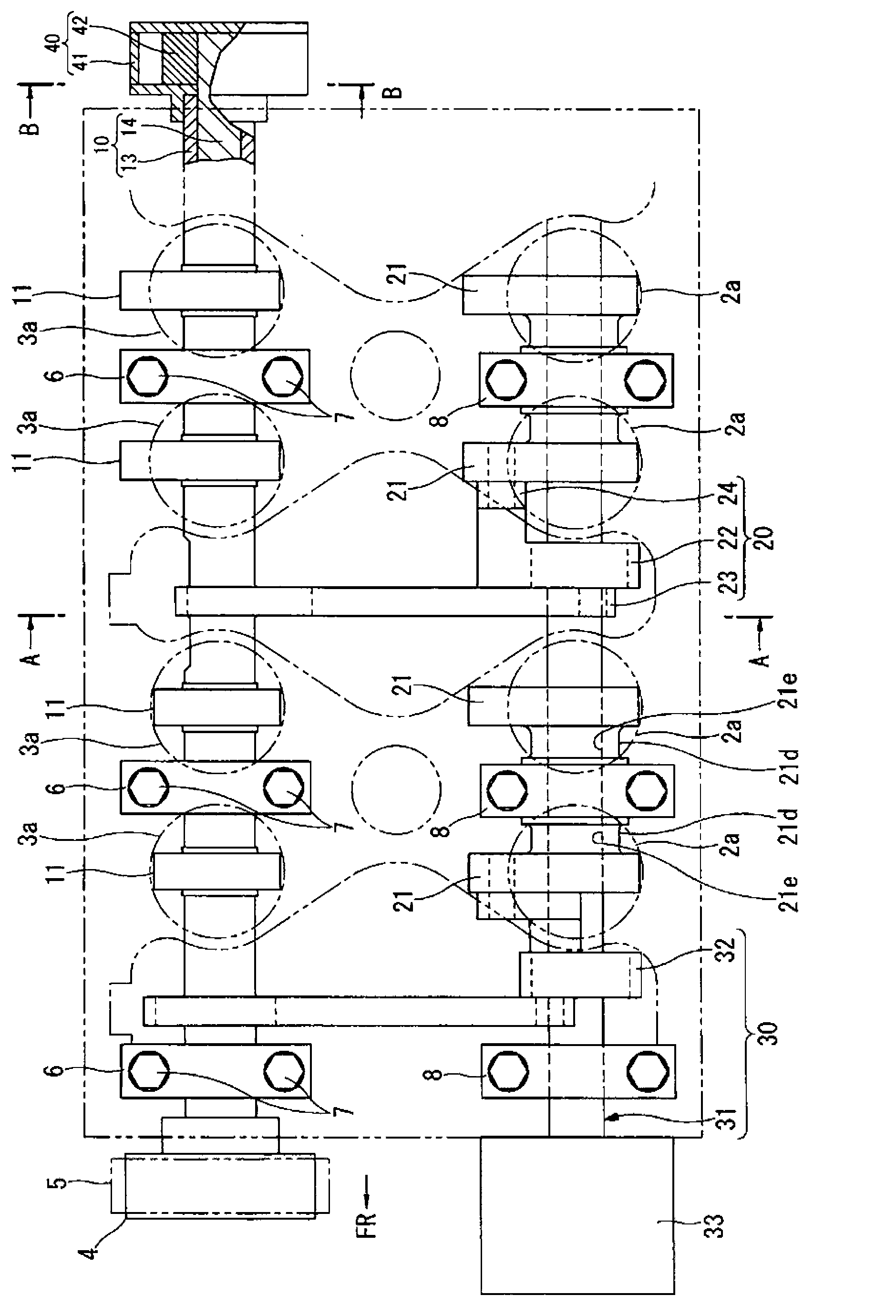
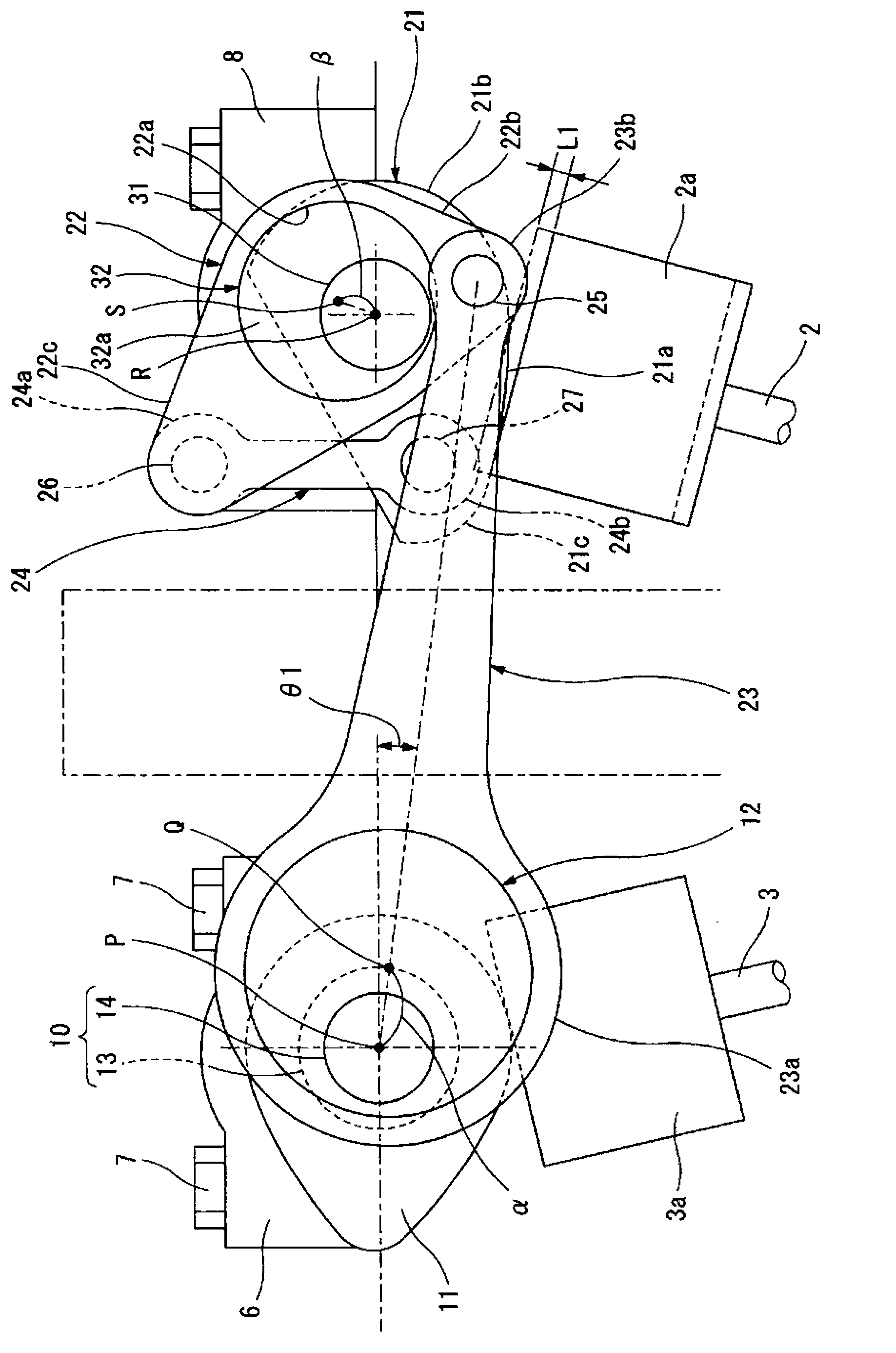
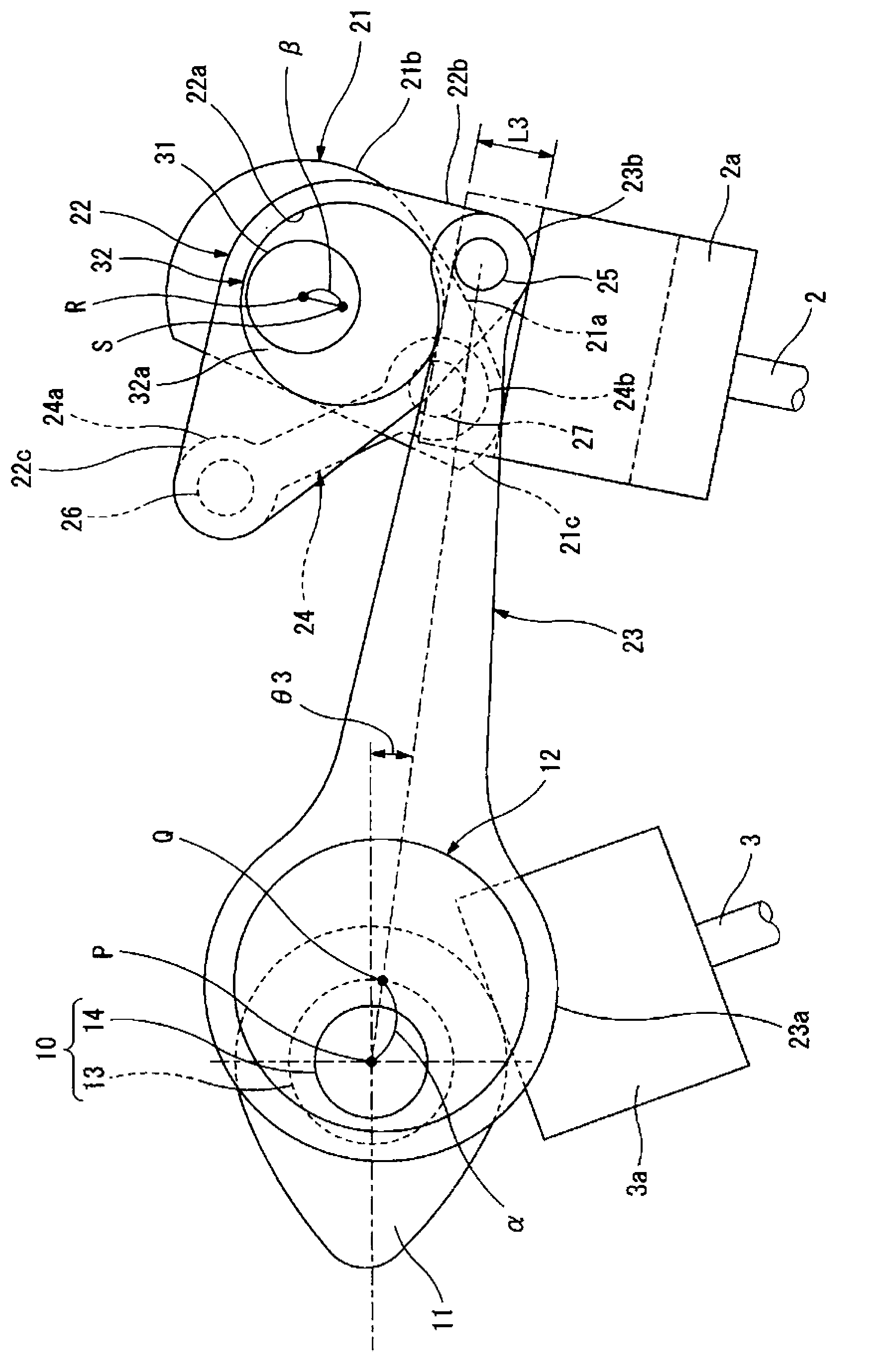
[0043] Hereinafter, each embodiment of the variable valve apparatus for an internal combustion engine according to the present invention will be described in detail with reference to the drawings. In addition, in each of these embodiments, the present invention is applied to a motor vehicle internal combustion engine having two intake valves and two exhaust valves per cylinder.

[0044] That is, if Figure 1~Figure 3As shown, the variable valve device includes: a control shaft 31 corresponding to the intake side camshaft, an exhaust side camshaft 10 forming a double structure described later, a transmission mechanism 20, and a control mechanism as a variable operating angle mechanism. 30. The control shaft 31 and the exhaust-side camshaft 10 are arranged side by side on both sides of the upper part of the cylinder head 1 along the front-rear direction of the internal combustion engine, and the transmission mechanism 20 will be integrally provided on the exhaust-side camshaft 1...


PUM


Abstract

The invention provides a variable valve apparatus for an internal combustion engine. The variable valve apparatus maintains good loading property and makes opening and closing periods of a valve of the internal combustion engine good. In the variable valve apparatus for the internal combustion engine, one of an intake valve and an exhaustvalve is driven by a rocker cam (21) of an operating angle variable mechanism, and the other one is driven by a rotary cam (11), wherein a camshaft (10) which is used to drive one of the valves of the internal combustion engine is made into a dual structure formed by an outer shaft (13) and an inner shaft (14). The two shafts (13,14) are structured to be able to control relative phase by using a phase control mechanism (40). The phase control mechanism (40) is formed by a cylindric housing (41) which is fixed on the outer shaft (13) and a blade rotor (42) which is fixed on the inner shaft (14).

Description

technical field [0001] The present invention relates to a variable valve device for an internal combustion engine that contributes to changing the opening and closing timing or valve lift amount of a valve of the internal combustion engine according to the operating state of the internal combustion engine. Background technique [0002] As a conventional variable valve device applied to an automotive internal combustion engine, a variable valve device described in, for example, the following Patent Document 1 is known. [0003] That is, this variable valve device is configured to drive the intake valve via an eccentric drive cam provided integrally with a camshaft disposed on the exhaust side via a swing cam supported on a control shaft disposed on the intake side, The exhaust valve is driven by a fixed cam integrally provided with the camshaft on the exhaust side, and the swing cam is rotatably supported on the rocker arm of the control cam fixed to the control shaft via a c...

Claims


Application Information

Patent Timeline
Patent Type & Authority Applications(China)
IPC IPC(8): F01L13/00
CPCF01L1/3442F01L13/0015F01L13/0026F01L2001/34453F01L2001/34469F01L1/044F01L2001/0473F01L2001/0537F01L2013/0073F01L1/10
Inventor 中村信
Owner HITACHI AUTOMOTIVE SYST LTD
Why Eureka
Try Eureka