
Bilateral double-spring driving unfolding mechanism

A deployment mechanism and dual-spring technology, which is applied to the power supply system of aerospace vehicles and other directions, can solve the problems of increasing the system weight and space requirements, increasing the risk of locking and positioning the deployment mechanism, and reducing product reliability, etc. Compact structure, reducing the impact force of deployment lock

Active Publication Date: 2013-08-21
BEIJING INST OF SPACECRAFT SYST ENG
View PDF3 Cites 25 Cited by
  • Summary
  • Abstract
  • Description
  • Claims
  • Application Information

AI Technical Summary

Problems solved by technology

The use of deployment mechanisms in pairs greatly increases the weight of the system and the use of space requirements, wasting resources and space; and the assembly of multiple deployment mechanisms requires coaxial installation, which makes assembly difficult due to manufacturing errors, and is affected by the space environment during on-orbit work It is easy to produce greater deformation and partial load, and even increase the risk of locking and positioning of the deployment mechanism, reducing product reliability

Method used

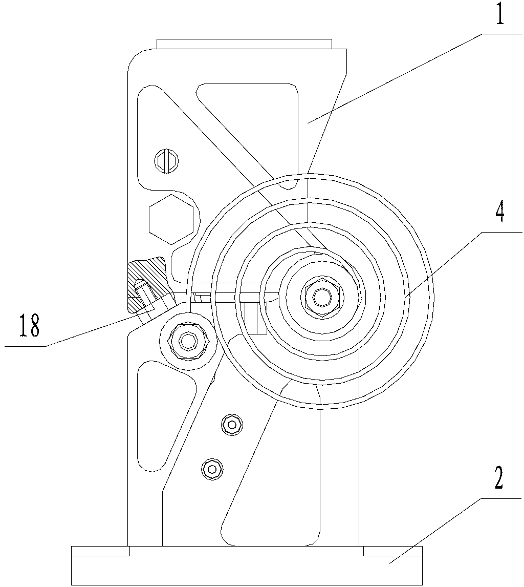
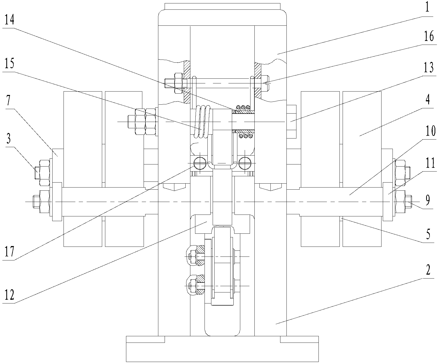
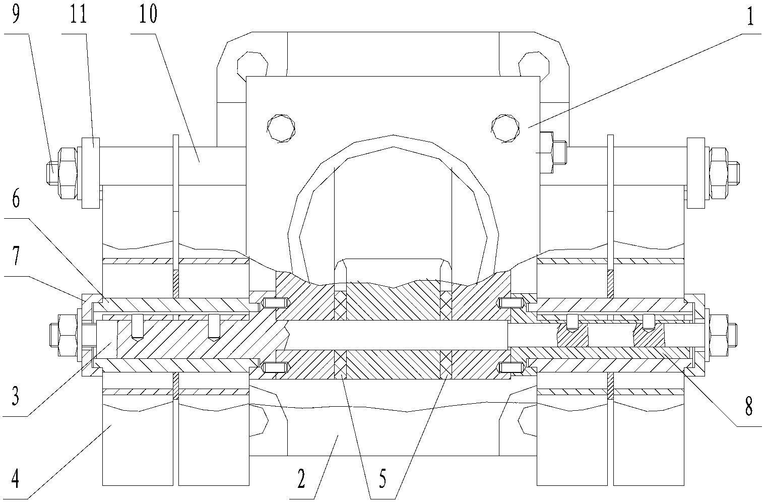

Image

  • Bilateral double-spring driving unfolding mechanism
  • Bilateral double-spring driving unfolding mechanism
  • Bilateral double-spring driving unfolding mechanism

Examples


Embodiment

[0025] As attached figure 1 , Attached figure 2 And image 3 As shown, a bilateral dual-spring drive expansion mechanism includes a living hinge 1, a fixed hinge 2, a concentric shaft 3, a scroll spring 4, a lubrication pad 5, a spring stop 6, a spring outer end cover 7, and a spring inner ring Fixed sleeve 8, spring outer ring fixed shaft 9, spring outer ring fixed sleeve 10, spring outer ring fixed sleeve gland 11, lock hook 12, lock hook rotation shaft 13, lock hook positioning sleeve 14, lock hook positioning torsion spring 15, The lock hook locates the torsion spring compression rod 16, the lock hook pad 17 and the limit screw 18.

[0026] Among them, the living hinge 1 and the fixed hinge 2 are both three-dimensional quadrangular structures, and are optimized for weight reduction according to topology optimization design technology, with grooves on each surface; the middle of the fixed hinge 2 is processed with slides and slides A section of arc-shaped protrusions is symme...


PUM


Abstract

The invention provides a bilateral double-spring driving unfolding mechanism. The unfolding mechanism comprises moving hinges, fixed hinges, concentric shafts, volute spiral springs, spring blocks, spring outer end covers, spring inner ring fixing sleeves, spring outer ring fixing shafts, spring outer ring fixing sleeves, spring outer ring fixing sleeve pressing covers, locking hooks, locking hook rotating shafts, locking hook locating sleeves, locking hook locating torsional springs, locking hook locating torsional spring pressing rods, limiting screws and a microswitch. The fixed hinges and the moving hinges achieve connection and a relative rotating function through the concentric shafts, four sets of bilateral plane volute spiral springs act on the fixed hinges and the moving hinges at the same time, the locking hook locating torsional pressing rods are matched with the locking hook locating torsional springs to enable locking shafts at the tail ends of the locking hooks to slide into the bottom faces of bosses on sliding rails of the fixed hinges, so that locking locating is finished, and meanwhile the microswitch is triggered to send a successfully arriving signal to a control system. The bilateral double-spring driving unfolding mechanism is relatively simple in achievement form, achieves a driving source redundant backup function, and is light in weight, compact in structure, high in reliability and strong in bearing capacity under the same driving capacity.

Description

Technical field [0001] The invention relates to an unfolding mechanism, in particular to a bilateral double-spring drive unfolding mechanism applied to the unfolding and positioning of the mechanism under the lunar gravity environment and planetary environment, and belongs to the technical field of spacecraft unfolding mechanisms. Background technique [0002] The unfolding mechanism of one-time action usually adopts the passive drive form of spring unfolding hinge. The locking and positioning forms mainly include mechanical locking, friction self-locking, etc., such as the hinge between the satellite solar wing panels. Due to the absence of gravity, the unfolding resistance moment is small. Only a single-sided spring is required to provide a driving torque to realize the deployment and positioning of the solar wing panel. However, with the continuous development of spacecraft technology, higher requirements have been put forward on the drive capability and working characteristic...

Claims


Application Information

Patent Timeline
Patent Type & Authority Applications(China)
IPC IPC(8): B64G1/42
Inventor 王有渔李新立刘宾王耀兵
Owner BEIJING INST OF SPACECRAFT SYST ENG
Learn More