Eureka AIR delivers breakthrough ideas for toughest innovation challenges, trusted by R&D personnel around the world.

Milling machining chatter active control system and method thereof

An active control system, milling technology, applied in automatic control devices, metal processing, metal processing equipment, etc., can solve the problems of high control cost, easy to break, small output force and displacement, etc., to achieve fast response, easy to control, The effect of large output force and displacement

Active Publication Date: 2015-05-20
HUST WUXI RES INST
View PDF6 Cites 0 Cited by
  • Summary
  • Abstract
  • Description
  • Claims
  • Application Information

AI Technical Summary

Problems solved by technology

For example, Zhang Yuanming et al. proposed a method of bonding piezoelectric ceramic actuators and thin-walled weakly rigid workpieces together to perform active chatter control (see "Milling Workpiece Chatter Avoidance Using Piezoelectric Active Damping: A Feasibility Study ", Smart Mater.Struct, 14 (6), N65-N70), this method has fast response, but it is easy to break, and the output force and displacement are small, which limits its application as a driver to a large extent; J.L.Dohner proposed a method of installing a magnetostrictive actuator on the main shaft to perform active chatter control (see "Mitigation of Chatter Instabilities in Milling by Active Structural Control", J.Sound Vibr, 2004, vol 269, pages 197-211 ), this method has fast response and large output force, but it is also easy to break and has the problem of high control cost

Method used


Image

  • Milling machining chatter active control system and method thereof
  • Milling machining chatter active control system and method thereof

Examples


Embodiment Construction

[0032] In order to make the object, technical solution and advantages of the present invention clearer, the present invention will be further described in detail below in conjunction with the accompanying drawings and embodiments. It should be understood that the specific embodiments described here are only used to explain the present invention, not to limit the present invention. In addition, the technical features involved in the various embodiments of the present invention described below can be combined with each other as long as they do not constitute a conflict with each other.

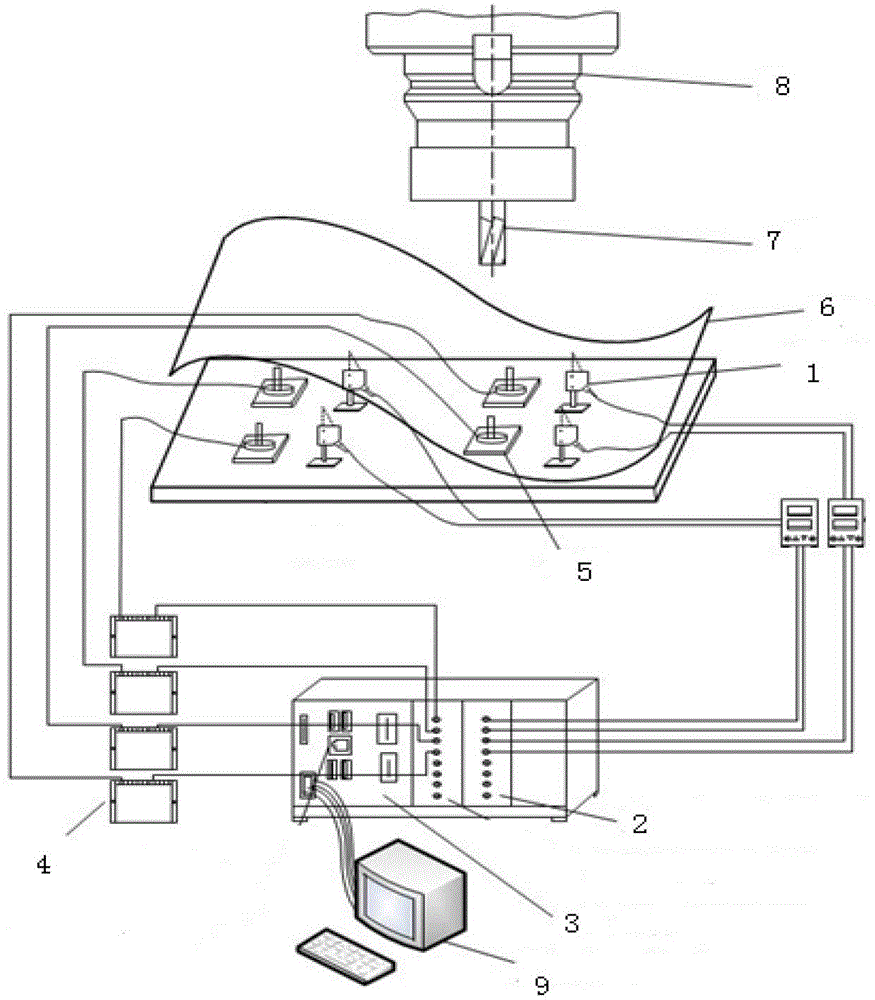
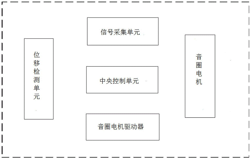
[0033] figure 1 It is a schematic diagram of the application environment of the milling chatter active control system according to the present invention, figure 2 It is a schematic diagram of the main structure of the milling chatter active control system according to the present invention. like figure 1 and figure 2 As shown in , the active chatter control system for milling according to ...


PUM


Abstract

The invention discloses a milling machining chatter active control system. The milling machining chatter active control system comprises a displacement detecting unit, a signal collecting unit, a central control unit, a voice coil motor driver and a voice coil motor, wherein the displacement detecting unit is used for executing sensing on workpiece displacement generated by chatter and obtaining a detected voltage signal, the signal collecting unit is used for collecting the detected voltage signal and transmitting the detected voltage signal to the central control unit, the central control unit correspondingly calculates a control voltage signal according to the received detected voltage signal, the voice coil motor driver converts the control voltage signal into a current signal, conducts power amplification, and then outputs the current signal to the voice coil motor for conducting driving, and therefore the active control process of milling machining chatter is achieved. The invention further discloses a corresponding control method. Through the milling machining chatter active control system and the control method, the chatter active control process can be executed in a mode which is quick in response, large in output force, and convenient to operate and control, the advantages of being high in precision, obvious in control effect and the like are achieved, and the milling machining chatter active control system and the control method are especially suitable for being used for the purposes of chatter control of workpieces like weak rigidity workpieces.

Description

technical field [0001] The invention belongs to the technical field of cutting processing control, and more specifically relates to a milling processing chatter active control system and a method thereof. Background technique [0002] During the milling process, due to the milling force and other uncertain loads, the process system often flutters, which affects the machining accuracy and milling efficiency. Chatter is a type of self-excited vibration, of which regenerative chatter (self-excited chatter induced by dynamic milling forces due to the effect of milling thickness variations) is the most harmful. The occurrence of chatter will reduce the amount of milling and the surface quality of the workpiece, leading to the early scrapping of processing tools and generating a lot of noise; The impact is particularly obvious. [0003] Aiming at the chatter phenomenon in the milling process, various active control technologies have been proposed in the prior art. One of the me...

Claims


Application Information

Patent Timeline
Patent Type & Authority Patents(China)
IPC IPC(8): B23Q15/12
Inventor 丁汉陈浦炜张海涛张小明
Owner HUST WUXI RES INST
Why Eureka
Eureka Blog
Learn More