piston unit

A technology of piston and radial piston engine, applied in the direction of piston, barrel piston, reciprocating piston engine, etc., to achieve the effect of improving starting efficiency and maximizing unloading force

Inactive Publication Date: 2016-01-13
ROBERT BOSCH GMBH
View PDF7 Cites 0 Cited by
  • Summary
  • Abstract
  • Description
  • Claims
  • Application Information

AI Technical Summary

Problems solved by technology

[0009] The last-mentioned disadvantage of the piston unit is the technical expenditure of the device in order to reduce the Hertzian stresses

Method used


Image

  • piston unit
  • piston unit
  • piston unit

Examples


Embodiment Construction

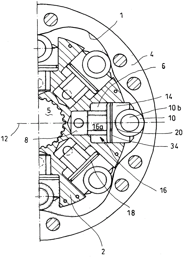
[0026] figure 1 A cutaway side view of a radial piston machine with a first exemplary embodiment of a piston unit 14 , 16 , 10 according to the invention is shown. The radial piston machine has an annular, undulating stroke cam 1 and eight cylinders 6, 8 with corresponding piston units 14, 16, 10, wherein in figure 1 Only three cylinders are shown in full and the other two cylinders are partially shown in . The cylinders 6 , 8 are arranged radially or star-shaped in the rotor 2 , while the travel cam 1 is formed on a disc cam 4 . The rotor 2 and the disc cam 4 are rotatable relative to each other. A radial piston machine of the type shown is usually used as a hydraulic motor, wherein the rotor can be fixed via a shaft 5 or a travel cam to the element to be driven.

[0027] Each cylinder 6 , 8 has a main section 6 and, on its side facing the shaft 5 , a radially stepped guide section 8 .

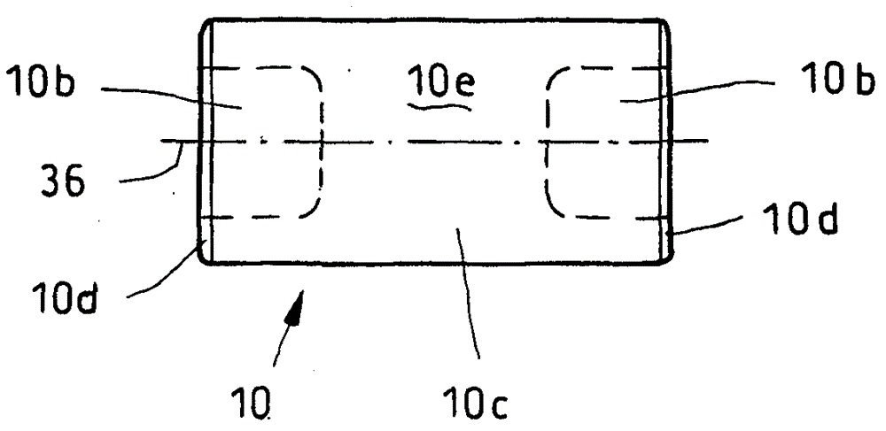
[0028] Each piston unit 14 , 16 , 10 has a roller 10 which, when the rotor 2 rotates,...


PUM


Abstract

The present invention relates to a piston unit for a radial piston machine, the piston unit having a piston and a roller or roller body, in addition to chamfering or similar structure, the roller or roller body having a cylindrical cover. In the equipment area between the piston and the roller, there is a hydrostatic pressure unloading device or force unloading device, which forms a pressure field here. Here, the roller has one or both end sides of the recess. By the concave parts (recesses), the rollers are slightly cut on the end segment of the mating, thereby reducing the Hertz stress here.

Description

technical field [0001] The invention relates to a piston unit for a radial piston machine according to the preamble of claim 1 , said piston unit comprising a piston and a roller. Background technique [0002] Various assembly methods (Ansatz) are known for piston units for radial piston machines. [0003] Document DE 4037455 C1 shows a radial piston machine with a plurality of cylinders arranged in a star shape in a rotor. Each cylinder is equipped with a piston unit. The piston unit has a multistage piston which is supported radially outwards via corresponding rollers on travel cams of the radial piston machine. Since the stroke cam is designed as a stator and has a wave shape, an oscillating stroke movement of the multistage piston is carried out for the rotating rotor. The roller is cylindrical over its entire length. [0004] A disadvantage of such piston units is the friction that occurs between the multistage pistons and the associated rollers. Furthermore, such ...

Claims


Application Information

Patent Timeline
Patent Type & Authority Patents(China)
IPC IPC(8): F04B1/04F04B1/107F01B13/06
CPCF04B1/0408F04B1/1071F16J1/00
Inventor P·纳格尔D·布罗伊尔G·克莫德K·蒂巴里
Owner ROBERT BOSCH GMBH
Why Eureka
Try Eureka