LED (light emitting diode) and manufacturing method thereof

A technology of light-emitting diodes and a manufacturing method, which is applied to electrical components, electrical solid-state devices, circuits, etc., can solve the problems of high power consumption, short life, short lighting time, etc., so as to improve the efficiency of light, prolong the life, The effect of reducing production cost and power consumption

Inactive Publication Date: 2013-08-14
东莞市星晖光电有限公司
View PDF3 Cites 1 Cited by
  • Summary
  • Abstract
  • Description
  • Claims
  • Application Information

AI Technical Summary

Problems solved by technology

[0003] At present, there are basically two types of fire emergency lights in the market. One is to use 8~12 plug-in LED light-emitting tubes. The problem with this kind of lights is that the power consumption is too large, and the lighting time in emergency is too short. ; The service life is not long, easy to decay
The second type is multiple SMD lamp beads: the cost of this product is more expensive; the power consumption is still large, and the brightness of the lamp is not enough
[0004] The existing technology is that there are three light-emitting chips in a single lamp bead, and its luminous efficiency is 125LM / W. It is driven by 60MA during operation, and the luminous flux is 22-24LM; the existing technology is driven by sufficient current, and its current value is close to that of the lamp bead. The upper limit, the amount produced will easily attenuate the lamp beads; in the prior art, each fire emergency product needs to use more than 3 lamp beads to meet its national standard requirements

Method used


Image

  • LED (light emitting diode) and manufacturing method thereof
  • LED (light emitting diode) and manufacturing method thereof

Examples


Embodiment 1

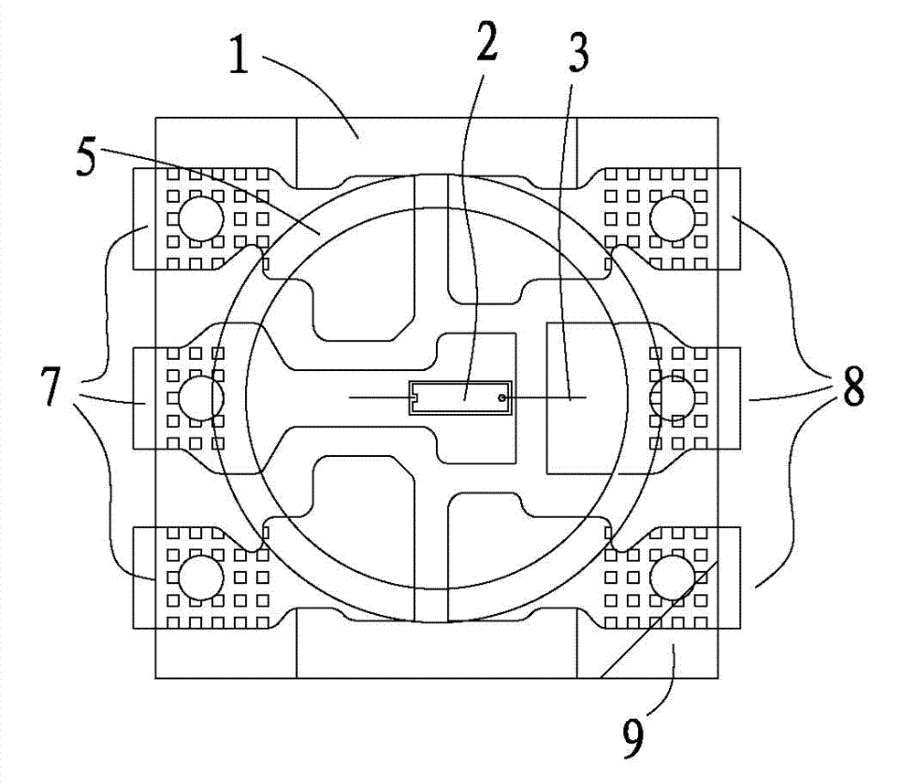
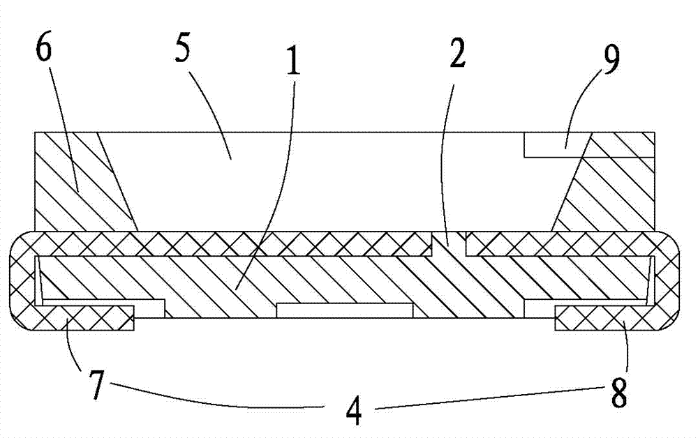
[0018] Example 1, Such as figure 1 , 2 As shown, the light-emitting diode includes a bracket 1, a light-emitting crystal 2, a gold wire 3, a power supply terminal 4, a phosphor layer 5 and a nylon layer 6, the light-emitting crystal 2 is bonded to the bracket 1, and the power supply terminal 4 passes through a gold wire 3 is electrically connected to the luminescent crystal 2, the phosphor layer 5 is coated on the luminescent crystal 2, and the nylon layer 6 is arranged around the phosphor layer 5.

[0019] Preferably, the power access terminal 4 includes a positive input terminal 7 and a negative input terminal 8, the number of the positive input terminal 7 and the negative input terminal 8 is set to three, and the three positive input terminals 7 and the three negative input terminals 8 are evenly distributed on both sides of bracket 1.

[0020] The phosphor layer 5 is arranged in a frustum-shaped structure, and the thickness of the phosphor layer 5 is 0.2-1 mm.

[0021...

Embodiment 2

[0023] Example 2 ,Such as figure 1 , 2 As shown, a method for manufacturing a light-emitting diode, the steps include: step 1, placing the light-emitting crystal 2 on the metal material in the middle of the bracket 1, bonding the light-emitting crystal 2 to the bracket 1 through an adhesive, and then baking treatment, so that the adhesive is completely cured; Step 2, electrically connect the light-emitting crystal 2 to the power supply terminal 4, and then perform the phosphor powder operation, so that the surface of the light-emitting crystal 2 is coated with a phosphor layer 5; Step 3, Then put it in a 90-degree oven and bake for 50 minutes, then transfer it to a 150-degree oven and bake for 2.5 hours, and finally get a light-emitting diode, which can be used normally after being tested and passed the test.

[0024] The phosphor point operation in the above step 2 includes the following steps: the first step is to mix the phosphor powder with a particle size of 15um and t...

Embodiment 3

[0028] Example 3, Such as figure 1 , 2 As shown, a method for manufacturing a light-emitting diode, the steps include: step 1, placing the light-emitting crystal 2 on the metal material in the middle of the bracket 1, bonding the light-emitting crystal 2 to the bracket 1 through an adhesive, and then baking treatment, so that the adhesive is completely cured; Step 2, electrically connect the light-emitting crystal 2 to the power supply terminal 4, and then perform the phosphor powder operation, so that the surface of the light-emitting crystal 2 is coated with a phosphor layer 5; Step 3, Then put it in a 90-degree oven and bake for 60 minutes, then transfer to a 150-degree oven and bake for 3 hours, and finally get a light-emitting diode, which can be used normally after being tested and passed the test.

[0029] The phosphor point operation in the above step 2 includes the following steps: the first step is to mix the phosphor powder with a particle size of 15um and the br...


PUM


Abstract

The invention belongs to the technical field of light-emitting components, and particularly relates to an LED which comprises a support, a light-emitting crystal, a gold line, a power supply access end, a fluorescent powder layer and a nylon layer, wherein the light-emitting crystal is bonded on the support; the power supply access end is electrically connected with the light-emitting crystal through the gold line; the light-emitting crystal is coated with the fluorescent powder layer; and the fluorescent powder layer is surrounded by the nylon layer. By virtue of the light-emitting crystal arranged on the support, the light efficiency is improved, and the production cost and the power consumption are reduced; and one the basis of the use of three light beads originally, one light bead is reduced, the service lives of the light beads are prolonged, and the energy-saving and electricity-saving effects are achieved. Besides, the invention further discloses a manufacturing method of the LED.

Description

technical field [0001] The invention belongs to the technical field of light-emitting elements, and in particular relates to a light-emitting diode and a manufacturing method thereof. Background technique [0002] A light emitting diode (Light Emitting Diode, LED) is a semiconductor element that converts electric current into light of a specific wavelength range. Light-emitting diodes can be widely used as light sources in the field of lighting because of their advantages such as high brightness, low operating voltage, low power consumption, easy matching with integrated circuits, simple driving, and long life. [0003] At present, there are basically two types of fire emergency lights in the market. One is to use 8~12 plug-in LED light-emitting tubes. The problem with this kind of lights is that the power consumption is too large, and the lighting time in emergency is too short. ; The service life is not long, easy to decay. The second type is multiple SMD lamp beads: the...

Claims


Application Information

Patent Timeline
Patent Type & Authority Applications(China)
IPC IPC(8): H01L33/52H01L33/50H01L25/075H01L33/00
CPCH01L2224/45144H01L2224/48247H01L2924/00
Inventor 肖明忠
Owner 东莞市星晖光电有限公司
Why Eureka
Try Eureka