An ejector pin assembly for lifting substrates
A technology of ejector rods and components, which is applied in the manufacture of electrical components, semiconductor devices, semiconductor/solid-state devices, etc., can solve problems such as breaking, not falling, deflection, etc., to reduce friction, smooth axial movement, and ensure smooth The effect of moving
- Summary
- Abstract
- Description
- Claims
- Application Information
AI Technical Summary
Problems solved by technology
Method used
Image

Examples
Embodiment 1
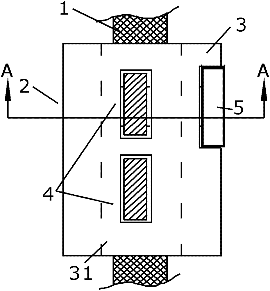
[0074] refer to image 3 As shown, the ejector pin assembly provided in this embodiment for lifting a substrate includes a ejector pin 1 and a guide device 2 for guiding the ejector pin 1 to move axially.
[0075] The guide device 2 includes a bracket 3, and the bracket 3 includes a through hole 31 that runs through the upper and lower end surfaces of the bracket 3 and is arranged axially along the push rod 1, and the push rod 1 is at least partially located in the through hole 31. Hole 31, so as to move axially. A plurality of guide mechanisms 4 are installed on the support 3 . The plurality of guide mechanisms 4 are arranged on the wall of the through hole 31 and evenly distributed around the push rod 1 . image 3 Among them, the plurality of guide mechanisms 4 are divided into two groups, distributed in a double-layer structure (only two of the guide mechanisms 4 are shown in the figure, and the rest are not shown). Wherein, the guide device 2 further includes an adjustm...
Embodiment 2
[0089] The technical solution of this embodiment is roughly the same as that of the above-mentioned embodiment 1, the difference is that the reference Figure 10 As shown, the adjustment mechanism 5 also includes an auxiliary adjustment plate 57 fixed on the bracket 3 . The auxiliary adjustment plate 57 is located at the other end of the roller 61 of the guide mechanism 6 , and the other end of the roller 61 is against the auxiliary adjustment plate 57 . When the adjustment plate 51 adjusts the position of the roller 62 on the bracket 3, the auxiliary adjustment plate 57 is used in conjunction with the adjustment plate 51 to assist the adjustment plate 51 to adjust the position of the roller. 61 position adjustment, thereby driving the roller 62 to adjust the position relative to the push rod 1 .
[0090] An auxiliary limit frame 33 for placing the auxiliary adjustment plate 57 is opened on the support 3 . Similar to the adjusting plate 51 and the limiting frame 32 in Embodi...
Embodiment 3
[0093] The scheme of this embodiment is roughly the same as that of Embodiment 1, the difference is that the reference Figure 12 As shown, the adjustment mechanism 5 includes an adjustment plate 51, and the adjustment plate 51 is fixed on the support 3; one end of the roller 61 of the guide mechanism 6 controlled by the adjustment mechanism 5 is provided with a spherical curved surface bump 9; The adjustment plate 51 is provided with a bump concave hole 54 matching the structure of the spherical curved surface bump 9 of the roller 61, and the spherical curved surface bump 9 is installed in the bump concave hole 54 to realize the rolling shaft 61. Connect with adjustment mechanism 5.
[0094] The guide mechanism 6 can also include a positioning bushing 63, the other end of the roller 61, that is, the end opposite to the spherical curved surface bump 9, is inserted in the positioning bushing 63, and the positioning shaft The inner diameter of the sleeve 63 is larger than the d...
PUM
 Abstract
Description
Claims
Application Information
 - R&D
- Intellectual Property
- Life Sciences
- Materials
- Tech Scout
- Unparalleled Data Quality
- Higher Quality Content
- 60% Fewer Hallucinations
Browse by: Latest US Patents, China's latest patents, Technical Efficacy Thesaurus, Application Domain, Technology Topic, Popular Technical Reports.
© 2025 PatSnap. All rights reserved.Legal|Privacy policy|Modern Slavery Act Transparency Statement|Sitemap|About US| Contact US: help@patsnap.com