
Outer calibration system for high-precision SAR (Synthetic Aperture Radar) active scaler

A calibrator and external calibration technology, which is applied in the field of remote sensing satellites, can solve the problems of large cumulative error, affecting measurement accuracy, and difficulty in polarization adjustment and alignment of transmitting and receiving antennas, and achieves a simple alignment method and convenient operation. Effect

Active Publication Date: 2013-08-14
INST OF ELECTRONICS CHINESE ACAD OF SCI
View PDF4 Cites 21 Cited by
  • Summary
  • Abstract
  • Description
  • Claims
  • Application Information

AI Technical Summary

Problems solved by technology

This method uses a separate measurement of G a , G T , G R , and then calculate σ according to the formula and the measured value. The disadvantage of this method is that the cumulative error of the test instrument used for three independent measurements will be large
[0007] Method 2: According to the inadequacies of method 1, an improved test method was proposed later, namely: the G a , G T , G R One-time measurement, the specific method is: arrange the receiving and transmitting antennas according to the far-field conditions, ensure that the polarization and pointing of the transmitting and receiving antennas are aligned correctly, measure the entire open-loop gain with an instrument, and then deduct the empty attenuation to measure σ. This method The cumulative error is avoided, but the instrument measurement error in the one-time measurement cannot be avoided, and during the test, there are great difficulties in the polarization adjustment and alignment of the transmitting and receiving antennas, and a very long RF cable is required to measure the open-loop gain. Lead to greater damage, but also affect the measurement accuracy

Method used


Image

  • Outer calibration system for high-precision SAR (Synthetic Aperture Radar) active scaler
  • Outer calibration system for high-precision SAR (Synthetic Aperture Radar) active scaler
  • Outer calibration system for high-precision SAR (Synthetic Aperture Radar) active scaler

Examples


Embodiment Construction

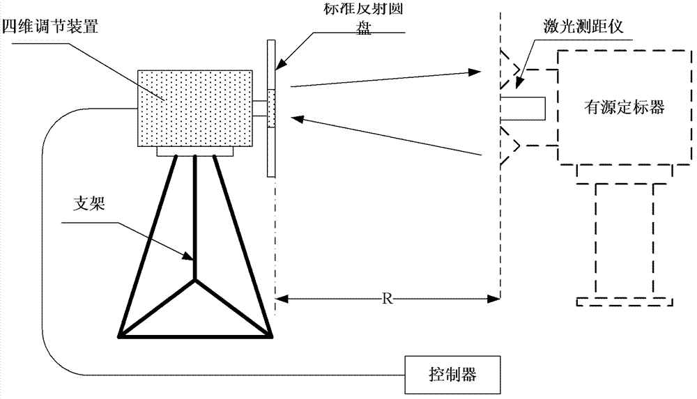
[0041] Considering the accumulative errors of instrument measurement, antenna alignment and fiber breakage errors in the two measurement methods of the prior art, the present invention proposes an external calibration system for SAR active scalers. The calibration principle is: active calibration When the scaler performs self-calibration, the transmitting antenna transmits a pulse signal of carrier frequency generated by the internal signal generator, and the receiving antenna receives the signal reflected by the standard reflector, and the reflected signal passes through the forwarding path of the active scaler After time-delay amplification, it is transmitted by the transmitting antenna, and the echo signal is sampled and recorded by the internal detection and recording system. Then the difference ΔP of the echo signal power recorded twice adjacently has the following relationship:

[0042] ΔP = σ 4 ...


PUM


Abstract

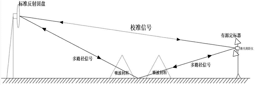
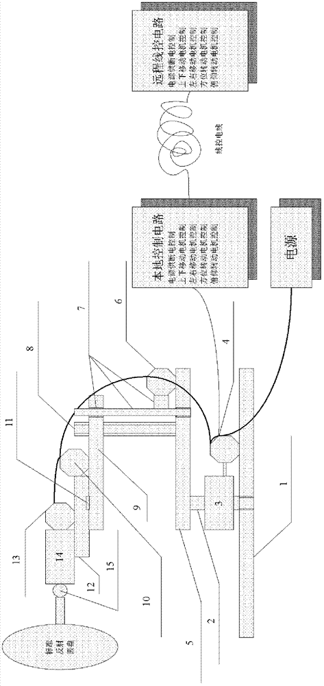
The invention discloses an outer calibration system for an SAR (Synthetic Aperture Radar) active scaler, and relates to the remote sensing satellite technology. The outer calibration system comprises a laser range finder, a standard reflection device, and wave-absorbing materials, wherein the laser range finder is fixed at the symmetric central line of a sending antenna and a receiving antenna of the active scaler through a switching device, and the fact that the direction which a laser beam points to is parallel to the mouth surface normals of the two antennas is ensured; the standard reflection device comprises a standard reflection disk, a four-dimensional adjusting mechanism and a support; the standard reflection disk can be used as a standard to reflect laser to further realize the alignment with the active scaler, has the function of reflecting electromagnetic signals and providing sectional area standard of a radar, and enables the active scaler to be aligned with the reflection disk through the servo transmission of the four-dimensional adjusting mechanism and the adjustment of a control mechanism; the support supports the standard reflection disk to a certain height; the wave-absorbing materials are laid at an appropriate position between the active scaler and the standard reflection disk to reduce the interference of multipath noise signals.

Description

technical field [0001] The invention relates to the technical field of remote sensing satellites, and relates to an external calibration system of a high-precision SAR active scaler, which is used for the self-calibration test of the SAR active scaler. Background technique [0002] The active calibrator needs to calibrate its nominal radar cross-section (RCS) value before use. There are two usual calibration methods: [0003] Method 1: Subsection measurement method, according to the calculation formula of active scaler RCS: [0004] σ = λ 2 4 π · G a G T G R [0005] Among them: σ represents the radar cross-sectional area of ​​the active scaler, λ represents the wavelength of electromagnetic waves, and G a Indicates the active scaler channel...

Claims


Application Information

Patent Timeline
IPC IPC(8): G01S13/90G01S7/40
Inventor 洪峻梁维斌郑寿庆朱勇涛李亮
Owner INST OF ELECTRONICS CHINESE ACAD OF SCI
Learn More