Motion compensation method for float-type high-frequency over-the-horizon radar

An over-the-horizon radar and motion compensation technology, applied in the fields of radio physics and marine science, can solve problems such as unsuitable buoy platforms, complex mechanical servo mechanisms, and large machinery

Inactive Publication Date: 2013-08-14
WUHAN UNIV
View PDF4 Cites 16 Cited by
  • Summary
  • Abstract
  • Description
  • Claims
  • Application Information

AI Technical Summary

Problems solved by technology

However, the structure of the mechanical servo mechanism is complicated, the machinery is huge, it is difficult to install and maintain, and it is not suitable for the buoy platform

Method used


Image

  • Motion compensation method for float-type high-frequency over-the-horizon radar
  • Motion compensation method for float-type high-frequency over-the-horizon radar
  • Motion compensation method for float-type high-frequency over-the-horizon radar

Examples


Embodiment Construction

[0076] The present invention will be further described below in conjunction with the embodiments shown in the accompanying drawings.

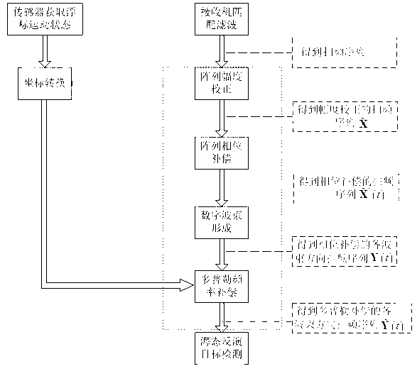
[0077] Such as image 3 Shown, the present invention comprises the following steps:

[0078] Step 1. Obtain the motion state parameters of the buoy platform, convert the coordinates of the parameters, map the motion state parameters under the buoy coordinate system to the earth coordinate system, and obtain the motion state parameters of the buoy platform under the earth coordinate system;

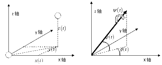
[0079] Based on the commonly used three-dimensional gyroscope and GPS positioning device on the buoy, six real-time parameters describing the motion state of the platform are obtained, including ψ(t), φ(t), x(t), y(t), z(t), ψ(t) are the rolling angles of the buoy, is the pitch angle of the buoy, φ(t) is the yaw angle of the buoy, x(t) represents the displacement of the buoy horizontally and laterally (along the x-axis), y(t) represents the displacement...


PUM


Abstract

The invention provides a motion compensation method for a float-type high-frequency over-the-horizon radar. The motion compensation method comprises the following steps: step 1, obtaining motion state parameters of a buoy platform, converting the coordinates of the motion state parameters, mapping the motion state parameters in a buoy coordinate system into a geodetic coordinate system, and obtaining motion state parameters of the buoy platform in the geodetic coordinate system; step 2, calculating array variations generated by the motion of the buoy platform, performing amplitude correction and phase compensation to a buoy radar array according to the array variations, and obtaining sweep frequency sequences after amplitude correction and phase compensation; and step 3, performing digital beam forming to the sweep frequency sequences obtained in step 2 so as to obtain sweep frequency sequences for all beam directions after phase compensation, and performing Doppler frequency compensation to radar received signals according to the motion state parameters of the buoy platform in the geodetic coordinate system obtained in step 1, and compensating the radar received signals from radar echo signals to obtain the sweep frequency sequences for all beam directions after Doppler frequency compensation. Therefore, the influence of the motion of the buoy platform to radar signals is reduced.

Description

technical field [0001] The invention belongs to the technical fields of radio physics and marine science, in particular to a motion compensation method for a buoy-type high-frequency over-the-horizon radar. Background technique [0002] High-frequency over-the-horizon radar is an effective tool for low-cost monitoring of the exclusive economic zone of the ocean. It is a high-tech ocean monitoring that has been developed internationally since the 1970s. High-frequency over-the-horizon radar utilizes the characteristics of high-frequency (3-30MHz) electromagnetic waves with small diffraction and propagation attenuation on the conductive ocean surface, uses vertically polarized antennas to radiate radio waves, and can detect ships, aircraft and missiles that appear below the line of sight of sea level over-the-horizon and other sports goals. At the same time, high-frequency over-the-horizon radar uses the first-order scattering and second-order scattering mechanisms of high-fr...

Claims


Application Information

Patent Timeline
IPC IPC(8): G01S7/02
Inventor 吴雄斌徐兴安陈骁锋李伦沈志奔马克涛王立
Owner WUHAN UNIV
Why Eureka
Try Eureka