Eureka AIR delivers breakthrough ideas for toughest innovation challenges, trusted by R&D personnel around the world.

Transmission source device

A transmission source and transmission hole technology, which is applied in the direction of material analysis using radiation, can solve the problems of radiation hazard, inability to achieve equivalent shielding, small shielding thickness, etc., and achieve the effect of reducing the received dose

Active Publication Date: 2013-08-14
CHINA INSTITUTE OF ATOMIC ENERGY
View PDF10 Cites 9 Cited by
  • Summary
  • Abstract
  • Description
  • Claims
  • Application Information

AI Technical Summary

Problems solved by technology

[0003] The conventional transmission source device has a transmission hole on the lead shielding body, and a movable stopper is installed outside the transmission hole to realize the switch of the transmission source. However, the movable stopper is generally controlled by a push rod motor. The transmission source cannot be automatically reset, and the risk of radiation exposure is prone to occur; in addition, the thickness of the movable stopper is smaller than the shielding thickness in other directions, and it is impossible to achieve all-round equivalent shielding

Method used


Image

  • Transmission source device
  • Transmission source device

Examples


Embodiment Construction

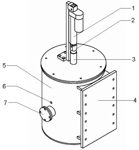
[0019] The specific operation method of using the transmission source shielding device to measure the transmission of the waste bin is as follows:

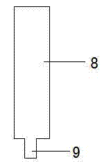
[0020] Open source: Before opening the source, the transmission source is in a safe position, the push rod motor controls the push rod 1 to go down, and when it touches the lead shielding rod 3, the electromagnet power is turned on, and the electromagnet attracts the lead shielding rod 3 of the transmission source. Control the push rod to go up, drive the lead shielding rod 3 to go up 5cm, so that the transmission source is facing the transmission hole 6, and the transmission source is in the open state. A fixing piece is installed on the outer side of the shielding body, and the fixing piece is connected with the motor guide rail outside the transmission device, and moves in the height direction of the waste bucket.

[0021] Closed source: After the transmission measurement is completed, control the push rod 1 to go down 5cm, tur...


PUM

PropertyMeasurementUnit
thicknessaaaaaaaaaa

Abstract

The invention belongs to the technical field of measurement of radioactive wastes and discloses a transmission source device. The device comprises a push rod, a lead shielding body and a lead shielding rod and is characterized in that a transmission source is located in a transmission source cavity at the lower part of the lead shielding rod; the bottom of the push rod is fixedly connected with an electromagnet; the lead shielding rod is located rightly below the electromagnet; a push rod motor controls the push rod to move downwards until the push rod is in contact with a stainless steel shell; the electromagnet is electrified to suck the lead shielding rod, and then the push rod motor moves upwards to bring the transmission source to the height of the position of a transmission hole, so that an opening function of the transmission source is realized; after transmission measurement is finished, the push rod motor moves downwards; after the transmission source reaches the position of a closed source shielding block below the transmission hole, the electromagnet is powered off and the lead shielding rod is released; and then the push rod motor is reset upward and a closing function of the transmission source is realized.

Description

technical field [0001] The invention belongs to the technical field of radioactive waste measurement, and in particular relates to a transmission source device. Background technique [0002] Quantitative measurement and analysis of gamma activity is carried out for large-volume nuclear materials or nuclear waste. The internal medium has a relatively large attenuation of gamma rays for radionuclides. The medium information is usually corrected by adding a transmission source measurement, and the selected transmission source is generally a strong gamma radiation source. During the use and operation of the strong gamma source, on the one hand, it is required to minimize the radiation dose of the transmission source to the operator during the normal use of the device; on the other hand, when an accident occurs, as long as the power is cut off quickly, the radiation The source quickly returns to a safe location. [0003] The conventional transmission source device has a transm...

Claims


Application Information

Patent Timeline
Patent Type & Authority Applications(China)
IPC IPC(8): G01N23/02
Inventor 柏磊邵婕文曹端程毅梅刘宏斌刘大鸣何丽霞王仲奇祝利群
Owner CHINA INSTITUTE OF ATOMIC ENERGY
Why Eureka
Eureka Blog
Learn More