
Hydraulic controllable reinforced concrete structure bottom form vertical support system and its construction method

A reinforced concrete, vertical support technology, applied in the direction of formwork/formwork/work frame, formwork/formwork/work frame connectors, pillars, etc., can solve the problem of different construction levels of workers, poor controllability of scaffolding, casualties, etc. Property and other issues, to achieve the effect of improving construction quality, ensuring continuous integrity, and high reuse rate

Active Publication Date: 2015-08-05
TIANJIN UNIV
View PDF6 Cites 0 Cited by
  • Summary
  • Abstract
  • Description
  • Claims
  • Application Information

AI Technical Summary

Problems solved by technology

In this operation, the construction level of the workers is different, and the subjective factors are relatively large, which makes the controllability of the loosening and re-fastening process of the scaffold poor, and it is easy to cause major construction accidents, resulting in casualties and property losses.

Method used


Image

  • Hydraulic controllable reinforced concrete structure bottom form vertical support system and its construction method
  • Hydraulic controllable reinforced concrete structure bottom form vertical support system and its construction method

Examples


Embodiment Construction

[0030] In order to further understand the invention content, characteristics and effects of the present invention, the following examples are given, and detailed descriptions are as follows in conjunction with the accompanying drawings:

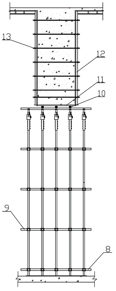
[0031] Such as figure 1 As shown, this embodiment firstly discloses a hydraulic controllable reinforced concrete structure bottom form vertical support system, which mainly consists of a jacking support 7, a hydraulic telescopic rod 6, a hydraulic press 4 with a pressure limiting valve 5, a connecting sleeve 2 and Scaffold pole 1 constitutes.

[0032] The bottom end of the jacking bracket 7 is welded to the top of the hydraulic telescopic rod 6, which is a steel arc groove structure with a diameter of 51 mm and a wall thickness of 3 mm.

[0033] The hydraulic telescopic rod 6 is provided with a scale mark, and the accuracy of the scale mark is millimeter (mm). The hydraulic telescopic rod 6 bottom is welded with the hydraulic press 4, and t...


PUM


Abstract

The invention discloses a hydraulic controllable vertical bracing system for a bottom form of a reinforced concrete structure and a method for constructing the hydraulic controllable vertical bracing system. The hydraulic controllable vertical bracing system comprises a hydraulic machine with a pressure limiting valve. The hydraulic machine is connected with a hydraulic telescopic rod with graduation marks, a carrying top support is welded on the top of the hydraulic telescopic rod, and a connecting sleeve which is in socket and spigot joint with an upright rod of a scaffold by plug pins is welded on the lower portion of the hydraulic telescopic rod. During superposition pouring construction, the hydraulic controllable vertical bracing system can be dimensionally and controllably retracted under the control of the pressure limiting valve, so that rigid bracing for the scaffold can be automatically and effectively released and unloaded, secondary rigid bracing for the scaffold can be automatically and effectively implemented, and construction load and the self-weight of concrete which is poured after secondary rigid bracing for the scaffold is implemented are effectively transmitted to a frame column; and the continuous springing height of the bottom form can be accurately controlled, so that the continuous springing integrity is guaranteed. Besides, precision construction for a reinforced concrete beam and the board bottom form from a construction springing step to a scaffold unloading step can be implemented by the hydraulic controllable vertical bracing system and the method, the hydraulic controllable vertical bracing system and the method have the advantages of simplicity and convenience in operation, high automation degree and visible and controllable bearing capacity values, the construction quality is effectively guaranteed, and the construction period is shortened.

Description

technical field [0001] The invention relates to the construction field of reinforced concrete structures in construction engineering, in particular to a reinforced concrete beam, a slab bottom form construction arching and a large-volume concrete transfer beam, and a bottom form support specially used for pouring by the slab superposition method. Background technique [0002] "Construction Quality Acceptance Code for Concrete Structure Engineering" requires that "for cast-in-place reinforced concrete beams and slabs with a span of not less than 4m, the formwork should be arched according to the design requirements; if there is no requirement, the arching height should be 1 / 1000 to 3 / 1000 of the span "The purpose of arching during construction is to overcome the sagging of the formwork itself under load. [0003] The method of on-site control of arching generally uses a level to measure the middle position of the positioning beam, the slab and the control elevations on both s...

Claims


Application Information

Patent Timeline
Patent Type & Authority Patents(China)
IPC IPC(8): E04G13/04E04G17/16E04G25/04
Inventor 丁红岩张磊张浦阳
Owner TIANJIN UNIV
Learn More