Communication Systems
A communication system and communication cable technology, applied in the field of communication, can solve problems such as limiting business data transmission and increasing switching delay, and achieve the effect of expanding business bandwidth and increasing density
- Summary
- Abstract
- Description
- Claims
- Application Information
AI Technical Summary
Problems solved by technology
Method used
Image


Examples
Embodiment 1
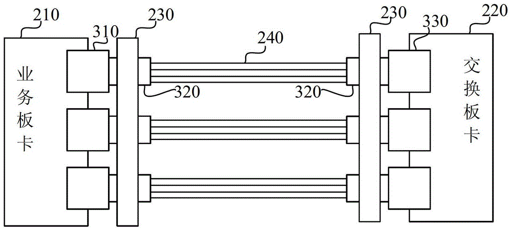
[0044] Such as figure 2 As shown, the communication system includes: a service board 210 , a switch board 220 , a backplane 230 and a communication cable 240 .
[0045] exist figure 2 , the service board 210 is connected to the backplane 230 for service processing;
[0046] The service board 210 is connected to the switch board 220 through the backplane 230 and the communication cable 240;
[0047] The switching board 220 is connected to the backplane 230, and is used for receiving the service data transmitted by the service board 210 and forwarding the service data.
[0048] Specifically, in the embodiment of the present invention, the number of service boards 210, switching boards 220, and backplanes 230 is greater than or equal to one. The communication cable 240 specifically includes cables and optical fibers.
[0049] Further, the service board 210 and the switching board 220 are connected to each other through the communication cable 240 drawn out from the backplan...
Embodiment 2
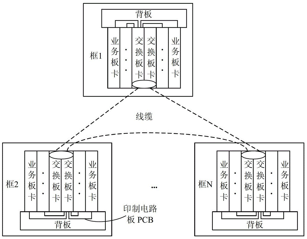
[0056] Optionally, in the embodiment of the present invention, the communication system can be further divided into a plurality of sub-frames, and the sub-frames are divided into a service frame and an exchange frame according to the board functions stored in them.
[0057] Specifically, the communication system further includes: at least one business frame and at least one exchange frame, such as Figure 4 As shown, any service frame includes at least one service board 210 and a backplane 230, and any switch frame includes at least one switch board 220 and a backplane 230.
[0058] exist Figure 4 In this method, the service boards 210 are centrally deployed in the service frame, and the switching boards 220 are centrally deployed in the switching frame. Connection; in the embodiment of the present invention, the backplane 230 further includes: power cables, control cables and data cables, thereby completing the interconnection of power supply, in-frame control, and data sig...
Embodiment 3
[0060] Optionally, in this embodiment of the present invention, the communication system may also be divided into multiple sub-frames, but the Figure 4 The communication system shown is different in that the sub-frame includes a service board 210 , a switching board 220 and a backplane 230 .
[0061] Specifically, the communication system further includes: at least one business processing box, such as Figure 5 As shown, any service processing frame includes at least one service board 210 , at least one switching board 220 and a backplane 230 .
[0062] exist Figure 5 , the service boards 210 and switching boards 220 are deployed in a distributed manner in the service processing frame, and the service boards 210 in the service processing frame are connected to the switching boards 220 outside the service processing frame through the backplane 230 and the communication cable 240 ;
[0063] The service board 210 in the service processing frame is connected with the switchin...
PUM
 Abstract
Description
Claims
Application Information
 - Generate Ideas
- Intellectual Property
- Life Sciences
- Materials
- Tech Scout
- Unparalleled Data Quality
- Higher Quality Content
- 60% Fewer Hallucinations
Browse by: Latest US Patents, China's latest patents, Technical Efficacy Thesaurus, Application Domain, Technology Topic, Popular Technical Reports.
© 2025 PatSnap. All rights reserved.Legal|Privacy policy|Modern Slavery Act Transparency Statement|Sitemap|About US| Contact US: help@patsnap.com