Eureka AIR delivers breakthrough ideas for toughest innovation challenges, trusted by R&D personnel around the world.
Device and method for measuring contact pressure of gyrounit
What is Al technical title?
Al technical title is built by PatSnap Al team. It summarizes the technical point description of the patent document.
A technology of contact pressure and gyro components, applied in the field of measurement, can solve the problems such as the small measuring range of the pointer type tension gauge, affecting the quality of product assembly, difficult to read accurately, etc., and achieves the effects of novel mechanical structure, improved test efficiency and convenient operation.
Inactive Publication Date: 2015-07-08
SHANGHAI JIAOTONG UNIV
View PDF7 Cites 0 Cited by
Summary
Abstract
Description
Claims
Application Information
AI Technical Summary
This helps you quickly interpret patents by identifying the three key elements:
Problems solved by technology
Method used
Benefits of technology
Problems solved by technology
The traditional method is to use a pointer-type tension gauge. During the test, the operator must observe the separation state of the contacts and read the pointer-type tension gauge. It is difficult to read accurately, which affects the assembly quality of the product and is inconvenient to operate.
In addition, the pointer type tension gauge also has the disadvantages of small measurement range and low measurement accuracy.
Method used
Image
Click on the blue label to locate the original text in one second.
Reading with bidirectional positioning of images and text.
Examples
Embodiment Construction
[0023] The present invention will be described in detail below in conjunction with specific embodiments. The following examples will help those skilled in the art to further understand the present invention, but do not limit the present invention in any form. It should be noted that those skilled in the art can make several modifications and improvements without departing from the concept of the present invention. These all belong to the protection scope of the present invention.
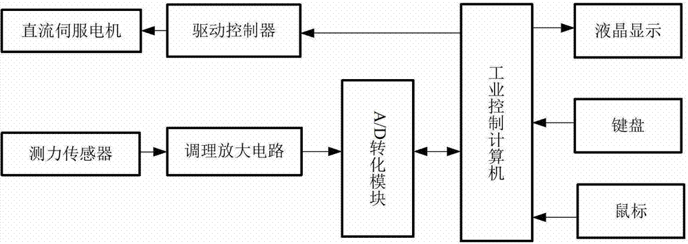
[0024] Please also see Figure 1 to Figure 2 A device for measuring contact pressure of gyroscope components, comprising: a mechanical part, an electrical part and an industrial control part, wherein the electrical part is connected to the mechanical part and the industrial control part respectively.
[0025] The mechanical part includes: deceleration mechanism 1, limit switch 2, screw rod 3, spiral copper sleeve 4, guide rod 5, copper sleeve 6, force sensor 7, cross bar 8, suspension wire 9, fixe...
PUM
Abstract
The invention provides a device for measuring contact pressure of a gyrounit. The device comprises a mechanical part, an electrical part and an industrial control part which are sequentially connected. The mechanical part comprises a speed reducing mechanism, a limit switch, a screw, a guiding rod, a pressure measurement sensor, a cross rod, a lifting rope, a fixed block, to-be-tested-workpiece mounting columns, a base, a left support plate, a right support plate and an upper cover plate, wherein the to-be-tested-workpiece mounting columns are connected with the left and the right support plates and the base, the upper cover plate is connected with the left and the right support plates, the speed reducing mechanism is connected to the upper portion of the upper cover plate, the screw is arranged below the upper cover plate and connected with the speed reducing mechanism, the guiding rod is connected to the upper cover plate and arranged close to the screw, the cross rod is connected with the screw and the guiding rod in sleeved manners, penetrates the right support plate and is arranged above the to-be-tested-workpiece mounting columns, the pressure measurement sensor and the fixed block are respectively connected with the cross rod, one end of the lifting rope is vertically suspended via the fixed block while the other end of the same is connected with the pressure measurement sensor, and the limit switch is connected with the left support plate. The device and the method for measuring the contact pressure of the gyrounit have the advantages of high measuring precision and efficiency, convenience in operation, and good repeatability.
Description
technical field [0001] The invention relates to the technical field of measurement, in particular to a measuring device and a measuring method for the contact pressure of gyroscope components. Background technique [0002] During the assembly and debugging process of the gyroscope, it is necessary to detect the contact pressure between the internal joint parts. The traditional method is to use a pointer-type tension gauge. During the test, the operator has to observe the separation state of the contacts and read the pointer-type tension gauge at the same time. It is difficult to read accurately, which affects the assembly quality of the product and is inconvenient to operate. In addition, the pointer type tension gauge also has the disadvantages of small measurement range and low measurement accuracy. Contents of the invention [0003] Aiming at the defects in the prior art, the object of the present invention is to provide a measuring device and method for measuring the ...
Claims
Application Information
Patent Timeline
Application Date:The date an application was filed.
Publication Date:The date a patent or application was officially published.
First Publication Date:The earliest publication date of a patent with the same application number.
Issue Date:Publication date of the patent grant document.
PCT Entry Date:The Entry date of PCT National Phase.
Estimated Expiry Date:The statutory expiry date of a patent right according to the Patent Law, and it is the longest term of protection that the patent right can achieve without the termination of the patent right due to other reasons(Term extension factor has been taken into account ).
Invalid Date:Actual expiry date is based on effective date or publication date of legal transaction data of invalid patent.