Imaging system for realizing multiple energy point spectrum resolution on extreme ultraviolet band and application of imaging system

An imaging system and spectral resolution technology, which is applied in the field of imaging systems that realize multi-energy point spectral resolution in the extreme ultraviolet band, can solve problems such as light collection efficiency (low ability to collect light, failure to meet diagnostic requirements, weak spectral selection ability, etc.) , to achieve the effect of improving light intensity, increasing brightness and high light collection efficiency

Inactive Publication Date: 2013-08-07
TONGJI UNIV
View PDF4 Cites 3 Cited by
  • Summary
  • Abstract
  • Description
  • Claims
  • Application Information

AI Technical Summary

Problems solved by technology

However, the spectral resolution of the pinhole camera is achieved by the filter placed in front of the detector. For the pinhole itself, it has no spectral selection ability, that is, the pinhole passes through any wavelength of light and cannot be selected. Imaging specific wavelengths of light
After combining the filter, the light with a certain wavelength can be selected, but the filter can pass light in a wide range o...

Method used


Image

  • Imaging system for realizing multiple energy point spectrum resolution on extreme ultraviolet band and application of imaging system
  • Imaging system for realizing multiple energy point spectrum resolution on extreme ultraviolet band and application of imaging system
  • Imaging system for realizing multiple energy point spectrum resolution on extreme ultraviolet band and application of imaging system

Examples


Embodiment 1

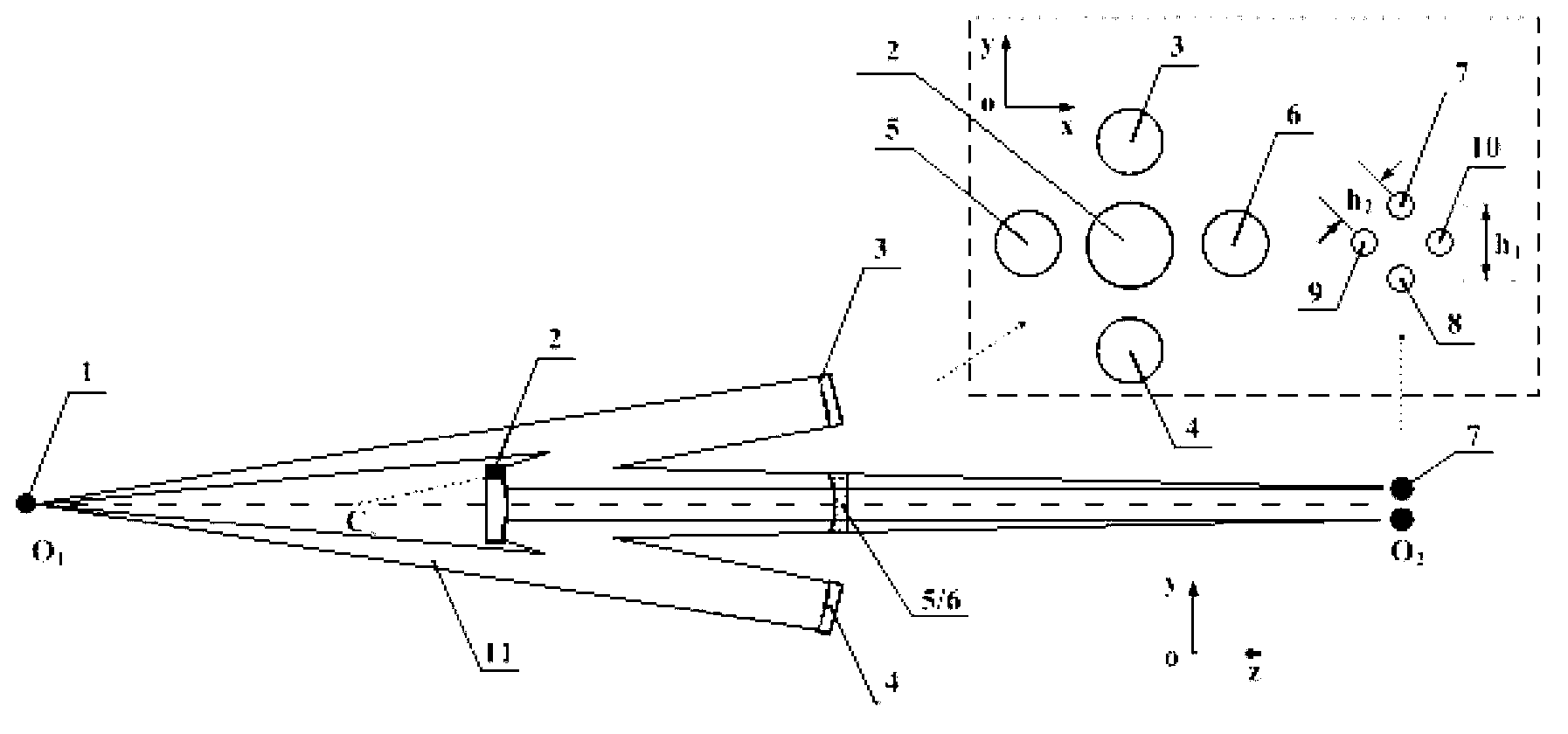
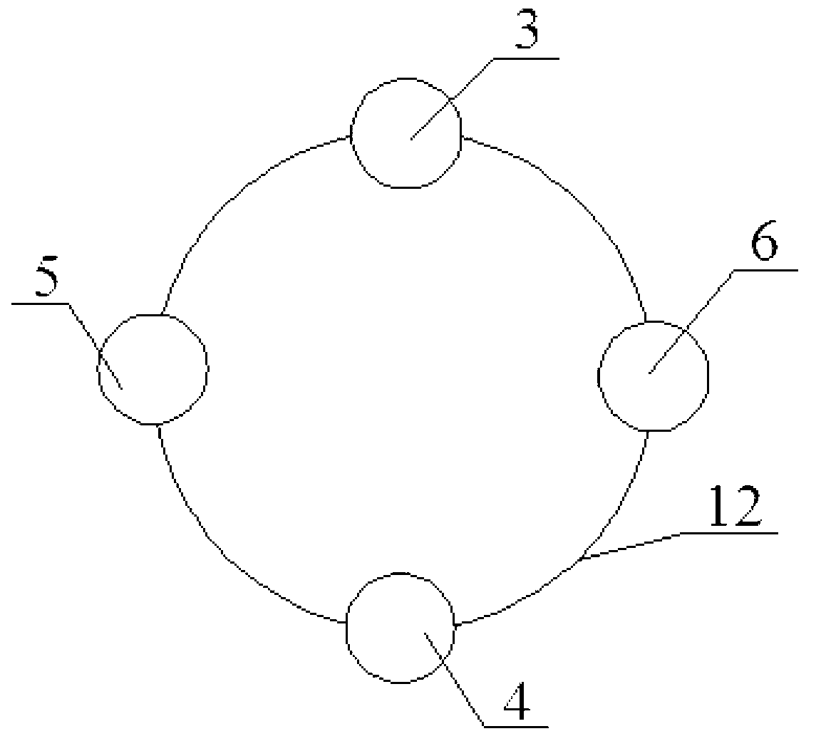
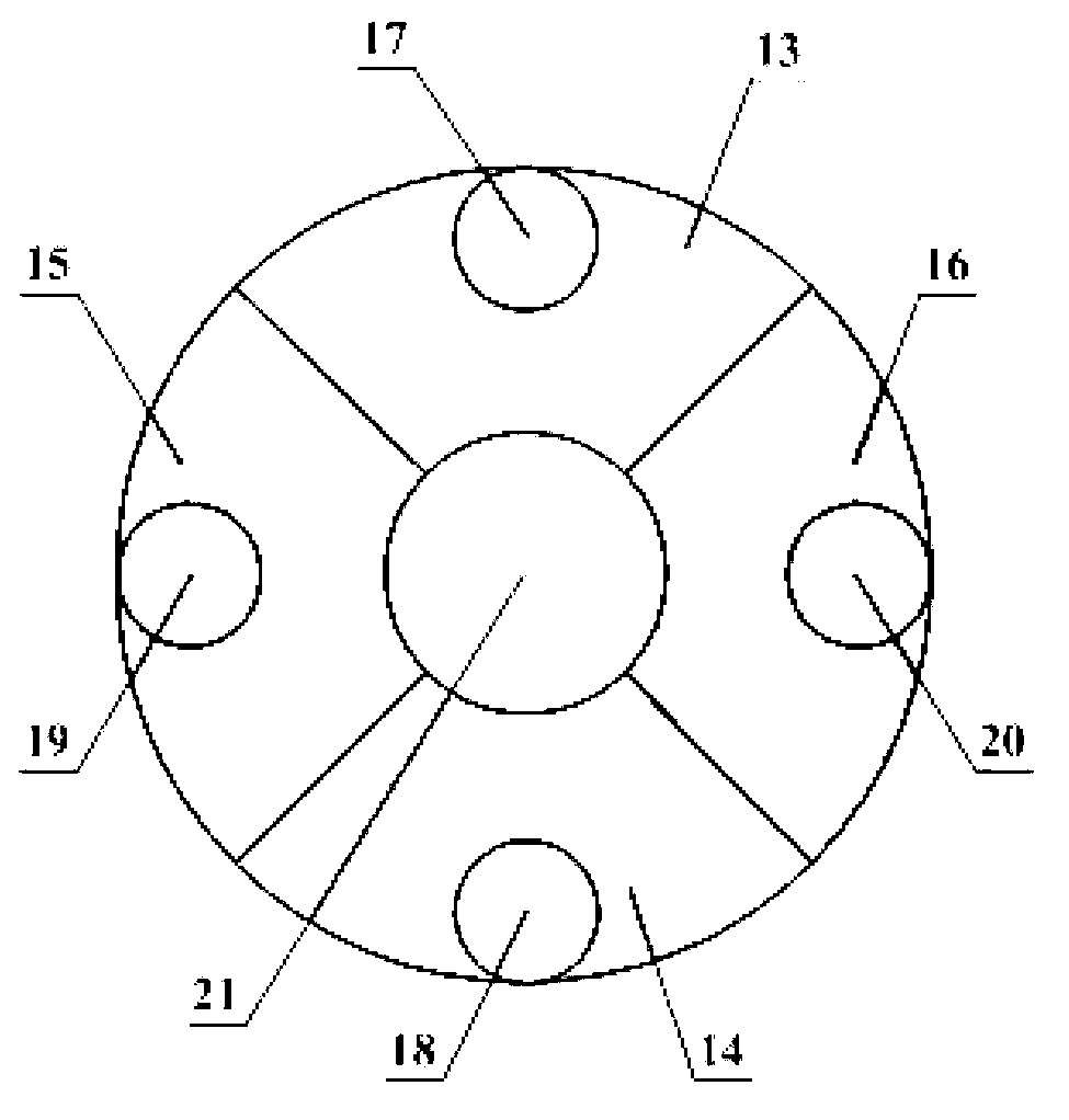
[0029] An imaging system that realizes multi-energy point spectral resolution in the extreme ultraviolet band, the working wavelength of the imaging system is extreme ultraviolet light or soft X-ray light. The imaging system is applied to image the plasma of the Z-pinch device. Such as figure 1 , figure 2 As shown, the system includes four primary mirrors (respectively the first primary mirror 3, the second primary mirror 4, the third primary mirror 5, and the fourth primary mirror 6) and a sub-mirror 2, the first primary mirror 3, the second primary mirror The second primary mirror 4, the third primary mirror 5, and the fourth primary mirror 6 are evenly arranged on a circle, and the secondary mirror 2 is located on the axis of the circle. Each primary mirror and the secondary mirror 2 jointly form a channel, and each channel An image is formed on the same object 1; after the extreme ultraviolet or soft X-ray 11 emitted by the object 1 is reflected by the first primary mir...

Embodiment 2

[0036] The difference from Embodiment 1 is that the system is an eight-channel system, which includes eight primary mirrors, such as Figure 5 As shown, the eight primary mirrors are all arranged on the same circumference 12, and the corresponding secondary mirrors 2 are divided into the same number of areas as the primary mirrors. The system includes 12 or more primary mirrors, and the corresponding secondary mirrors 2 are divided into the same number of areas as the primary mirrors.


PUM

PropertyMeasurementUnit
Spectral bandwidthaaaaaaaaaa

Abstract

The invention relates to an imaging system for realizing multiple energy point spectrum resolution on the extreme ultraviolet band and an application of the imaging system. The imaging system comprises a plurality of main mirrors and an auxiliary mirror; all the main mirrors are arranged in a circle; the auxiliary mirror is arranged on an axis of the circle; one channel is formed by combination of each main mirror and the auxiliary mirror; and one image is formed in each channel for the same object. Light emitted from the object is reflected via each main mirror, then is irradiated to the auxiliary mirror, and finally is reflected by the auxiliary mirror to form a plurality of images with a number as the same as the number of the main mirrors. The imaging system is applied to imaging of plasma of a Z-pinch device; plasma images, of ultraviolet band, with multiple energy point and high spectrum resolution can be acquired in one-step imaging; and research on an evolutionary process of the plasma at different temperatures along with time is facilitated. Compared with the prior art, the imaging system has the advantages of multiple energy point imaging, high light concentrated efficiency, high spectrum resolution and the like.

Description

technical field [0001] The invention relates to the field of extreme ultraviolet imaging, in particular to an imaging system for realizing spectral resolution of multi-energy points in the extreme ultraviolet band and an application thereof. Background technique [0002] The high-power Z-pinch device can generate strong X-ray pulses, and has important application prospects in the research of radiation characteristics of materials and devices, controllable fusion and nanolithography. Imaging systems with spectrally selective capabilities can capture the radiation profile of plasmas at specific temperatures. At present, the commonly used imaging equipment at home and abroad in Z-pinch device plasma diagnosis includes: pinhole camera, grazing incidence imaging system and normal incidence imaging system. The pinhole camera is based on the principle of "small hole imaging". The Z-pinch target is imaged on the image plane after passing through a pinhole with a diameter of about t...

Claims


Application Information

Patent Timeline
IPC IPC(8): G01J3/28
Inventor 穆宝忠王新伊圣振王占山朱京涛
Owner TONGJI UNIV
Why Eureka
Try Eureka