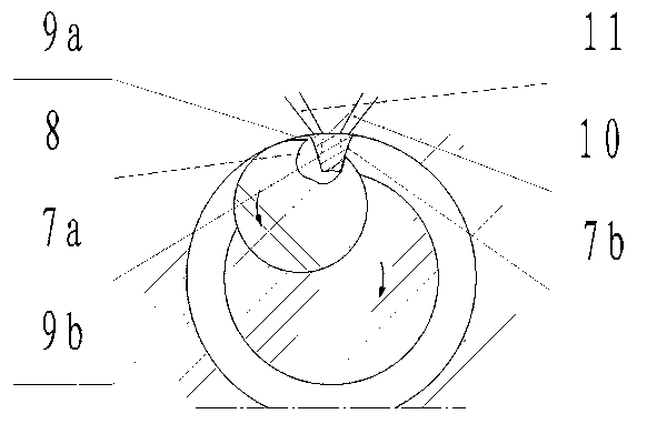
Cock-type rotary compression expansion mechanism
An expansion mechanism and rotary compression technology, which is applied in the direction of rotary piston machinery, rotary piston pump, internal combustion piston engine, etc., can solve the problems of triangular rotor engine with small output torque, difficulty in increasing compression ratio, and difficulty in large-scale promotion. Achieve the effect of large output torque, small free volume and high mechanical efficiency
- Summary
- Abstract
- Description
- Claims
- Application Information
AI Technical Summary
Problems solved by technology
Method used
Image
Examples
Embodiment 1
[0034] Embodiment 1: A cock type double-cylinder rotary compression mechanism.
[0035] image 3Shown is a plug-type twin-cylinder rotary compression mechanism. In the figure, a plug-type double-cylinder rotary compression mechanism composed of two convex plugs 5 and two cocks 6 is used; the two convex plugs 5 isolate the annular closed space into two arc-shaped working chambers (double cylinders) , The convex plug 5 works in the gas isolation mode, and the two sides of the convex plug 5 are provided with an air inlet 10 and an exhaust port 11; the side plates are fixed on both ends of the base cylinder of the rotor 3, forming the main body of the cock type double-cylinder rotary compression mechanism. The rotor 3 drives the cock 6 to rotate continuously at a constant speed, the rotation speed ratio between the rotation of the rotor 3 and the reverse rotation of the cock 6 is 1:1 (the relative speed ratio between the cock 6 and the rotor 3 is 2:1), and the rotor 3 rotates onc...
Embodiment 2
[0037] Embodiment 2: A cock type single-cylinder rotary expansion mechanism.
[0038] Figure 4 Shown is a plug-type single-cylinder rotary expansion mechanism. In the figure, a cock-type single-cylinder rotary expansion mechanism consisting of a cock 6, a convex plug 5 and a transition plug 14 is used; there is a sufficient gap between the transition plug 14 and the rotor base circle 4, so as not to block the air passage, only in the The cock 6 plays a sealing role when it passes through; the convex plug 5 works in the gas isolation mode, and the two sides of the convex plug 5 are provided with an air inlet 10 and an exhaust port 11; the high-pressure air inlet is equipped with a gas distribution valve; the side plate is fixed on the rotor base The two ends of the cylinder form the main body of the cock type single-cylinder rotary expansion mechanism. The cock 6 pushes the rotor 3 to rotate continuously at a constant speed. The rotation speed ratio between the rotation of t...
Embodiment 3
[0040] Embodiment 3: A cock-type double-cylinder rotary compression-expansion mechanism.
[0041] Figure 5 Shown is a cock-type twin-cylinder rotary compression-expansion mechanism. Figure 6 It is a three-dimensional schematic diagram. In the figure, a plug-type double-cylinder rotary compression-expansion mechanism composed of two convex plugs 5 and two cocks 6 is used; the two convex plugs 5 isolate the annular closed space into a compression chamber and an expansion chamber (double-cylinder ); in the figure, the left convex plug works in gas isolation mode, and there are air inlet 10 and exhaust port 11 on both sides of the convex plug; the right convex plug works in gas transposition mode, and the expansion side can be equipped with ignition device or fuel injection Device; the side plates 13 are fixed on both ends of the base cylinder of the rotor 3, forming the main body of the cock type double-cylinder rotary compression expansion mechanism. The rotor 3 drives the ...
PUM
 Abstract
Description
Claims
Application Information
 - R&D
- Intellectual Property
- Life Sciences
- Materials
- Tech Scout
- Unparalleled Data Quality
- Higher Quality Content
- 60% Fewer Hallucinations
Browse by: Latest US Patents, China's latest patents, Technical Efficacy Thesaurus, Application Domain, Technology Topic, Popular Technical Reports.
© 2025 PatSnap. All rights reserved.Legal|Privacy policy|Modern Slavery Act Transparency Statement|Sitemap|About US| Contact US: help@patsnap.com


