
Cell handover method, equipment and system for monitor terminal

A cell handover and terminal technology, applied in electrical components, wireless communication, etc., can solve problems such as inability to receive RRC connection reconfiguration messages, inability to switch, etc.

Active Publication Date: 2013-07-31
TD TECH COMM TECH LTD
View PDF4 Cites 46 Cited by
  • Summary
  • Abstract
  • Description
  • Claims
  • Application Information

AI Technical Summary

Problems solved by technology

Since the RRC connection is established between the speaker terminal and the network side, the above method can still be used, and the speaker terminal sends a special RRC connection reconfiguration message for handover, measurement, and other configurations to achieve handover and other processes; however, monitoring There are a large number of terminals, and some monitoring terminals have established RRC connections with the network side, so they are in the connected state, while some monitoring terminals have not established RRC connections with the network side, so they are in the idle state
For the monitoring terminal in the connected state, the above method can still be used to send RRC connection reconfiguration messages for the corresponding monitoring terminal to perform handover, measurement and other configurations to achieve switching and other processes; and for the monitoring terminal in the idle state due to The RRC connection has not been established, so the RRC connection reconfiguration message cannot be received, and the above method cannot be used to achieve switching

Method used


Image

  • Cell handover method, equipment and system for monitor terminal
  • Cell handover method, equipment and system for monitor terminal
  • Cell handover method, equipment and system for monitor terminal

Examples


Embodiment Construction

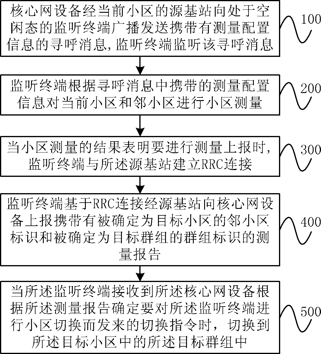
[0036] figure 1 It is a flow chart of an embodiment of the cell switching method of the monitoring terminal according to the present invention, as shown in the figure, including the following steps:

[0037] Step 100 , the core network equipment broadcasts and sends a paging message carrying measurement configuration information to a monitoring terminal in an idle state via a source base station of the current cell, and the monitoring terminal monitors the paging message.

[0038] Wherein, the current cell refers to the cell where the monitoring terminal is currently located; the idle state refers to a state in which the monitoring terminal is in a state where an RRC connection has not been established with the network side; the paging message specifically carries the measurement configuration information The system information block type (System Information Block Type, referred to as: SIB) 20 system message, this message is an information element (Information Element, referre...


PUM


Abstract

The invention provides a cell handover method, cell handover equipment and a cell handover system for a monitor terminal. The cell handover method comprises the steps as follows: an idle monitor terminal in the current cell monitors a paging message transmitted from core network equipment via a source base station; the monitor terminal measures the current cell and an adjacent cell according to measurement configuration information contained in the paging message; when the results of cell measurement shows that measurement report is carried out, an RRC (Connection Reconfiguration) connection between the monitor terminal and the resource base station is established; based on the RRC connection, the monitor terminal submits a measurement report containing a mark of the adjacent cell determined as a target cell and another mark of a group determined as a target group for the core network equipment via the resource base station; and when the monitor terminal receives a handover instruction transmitted from the core network equipment according to the measurement report determining to carry out cell handover for the monitor terminal, the monitor terminal is switched to the target group of the target cell. According to the invention, the idle monitor terminal also can achieve cell handover.

Description

technical field [0001] The present invention relates to a cell switching method, device and system for monitoring terminals, and belongs to the technical field of long term evolution (Long Term Evolution, LTE for short) trunking communication. Background technique [0002] Trunking communication technology is a single-to-multipoint half-duplex wireless communication technology; LTE trunking communication technology is a trunking communication technology based on LTE technology. [0003] According to the existing LTE technical standards, when a terminal establishes a wireless link with a cell, the base station generally performs RRC connection reconfiguration for the user through Layer 3 Radio Resource Control (RRC) signaling, specifically in the RRC The connection reconfiguration message (RRC Connection Reconfiguration) carries measurement configuration information, so that the terminal can perform neighbor cell measurement according to the measurement configuration informat...

Claims


Application Information

Patent Timeline
IPC IPC(8): H04W36/08H04W24/00
Inventor 王大飞高红梅王亮
Owner TD TECH COMM TECH LTD
Learn More