Emergency reactor core cooling system, and boiling-ater nuclear power plant
A technology of accident cooling and atomic energy, applied in cooling devices, auxiliary equipment of nuclear power plants, reactors, etc., to avoid system loss of function and minimize the number of systems
- Summary
- Abstract
- Description
- Claims
- Application Information
AI Technical Summary
Problems solved by technology
Method used
Image

Examples
no. 1 approach
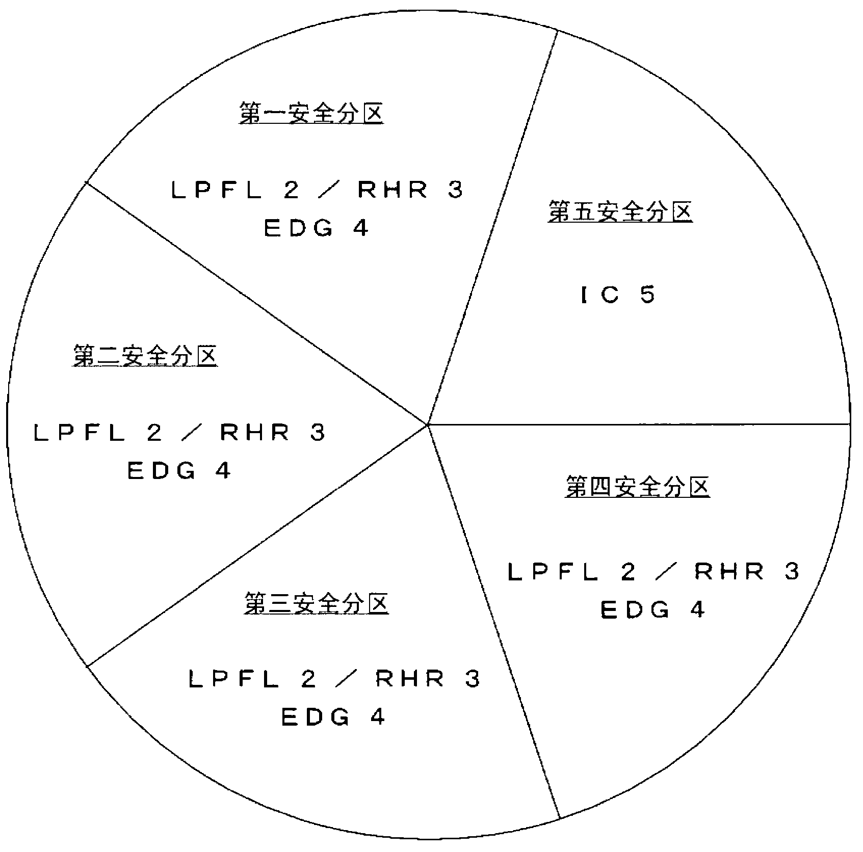
[0047] use figure 1 A first embodiment of the core emergency cooling system according to the present invention will be described.
[0048] figure 1 It is a figure which shows the structure of the core emergency cooling system which concerns on the 1st Embodiment of this invention. The core accident cooling system in this embodiment is composed of the first, second, third and fourth safety partitions dedicated to the dynamic core accident cooling system and the fifth safety partition including the static core accident cooling system, a total of five safety partitions . In the first, second, third, and fourth safety zones dedicated to the dynamic core accident cooling system, a low-pressure core cooling system (LPFL) 2 is provided as an electric-driven low-pressure core cooling system, as a A residual heat removal system (RHR) that shares a part of the pump and piping of the system 2 is provided with a residual heat removal system 3 , and a backup diesel generator (EDG) 4 i...
no. 2 approach
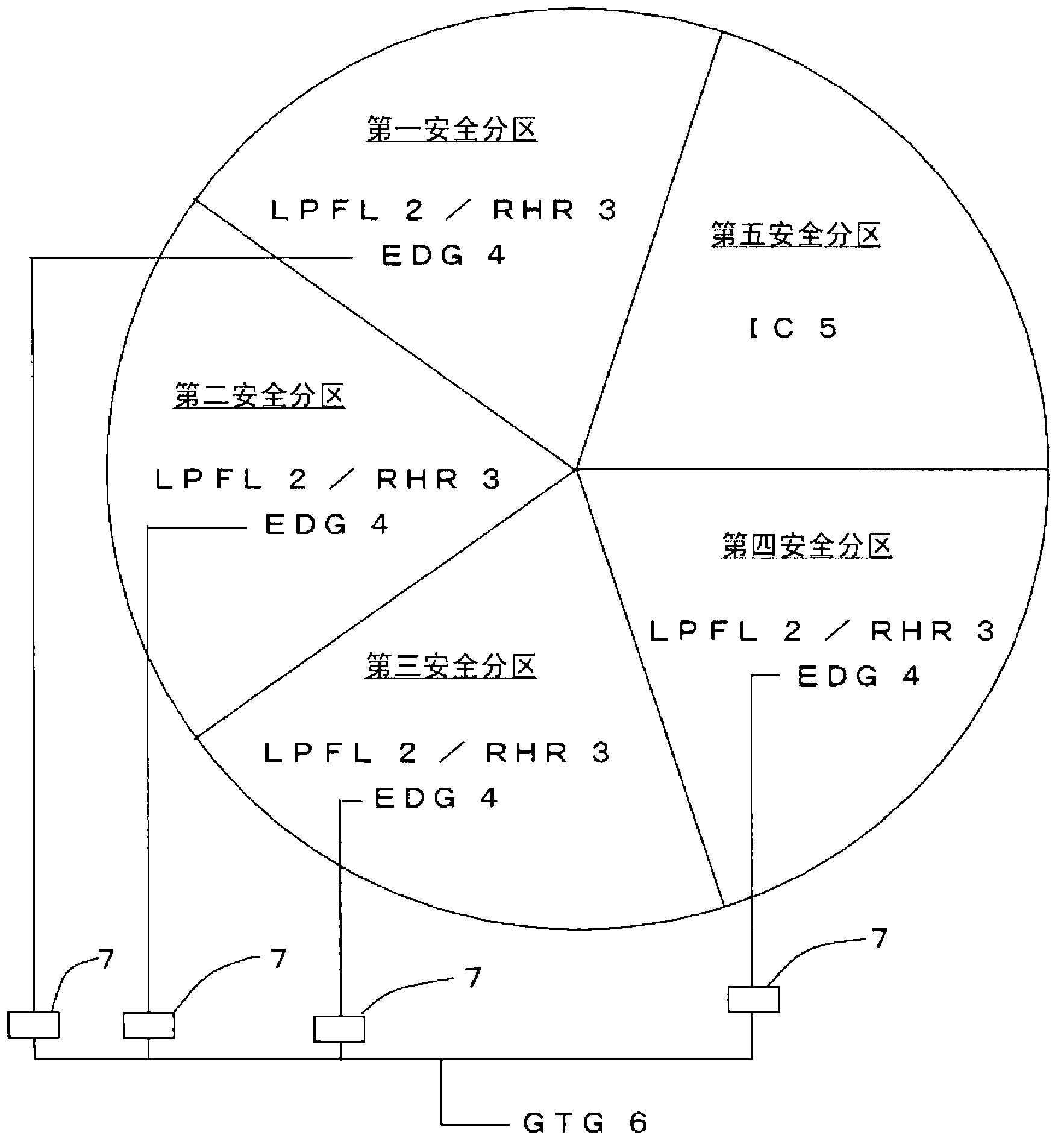
[0069] Secondly, figure 2 It is a diagram showing the configuration of a core emergency cooling system according to a second embodiment of the present invention. In this embodiment, only one gas turbine generator 6 is provided as an auxiliary power supply, which is shared in all the safety zones dedicated to the dynamic core emergency cooling system, and can be switched to any of the safety zones dedicated to the dynamic core emergency cooling system. One for power supply. Since it is possible to switch to each dynamic safety zone and supply power from the gas turbine generator 6 , it is possible to switch and supply power from the gas turbine generator 6 to the power supply bus of each dynamic safety zone via the disconnector 7 .
[0070] In the present embodiment configured as described above, the safety against the loss of all AC power sources during the operation of the facility is improved. In addition, the diversity of power sources can be secured even when only four ...
no. 3 approach
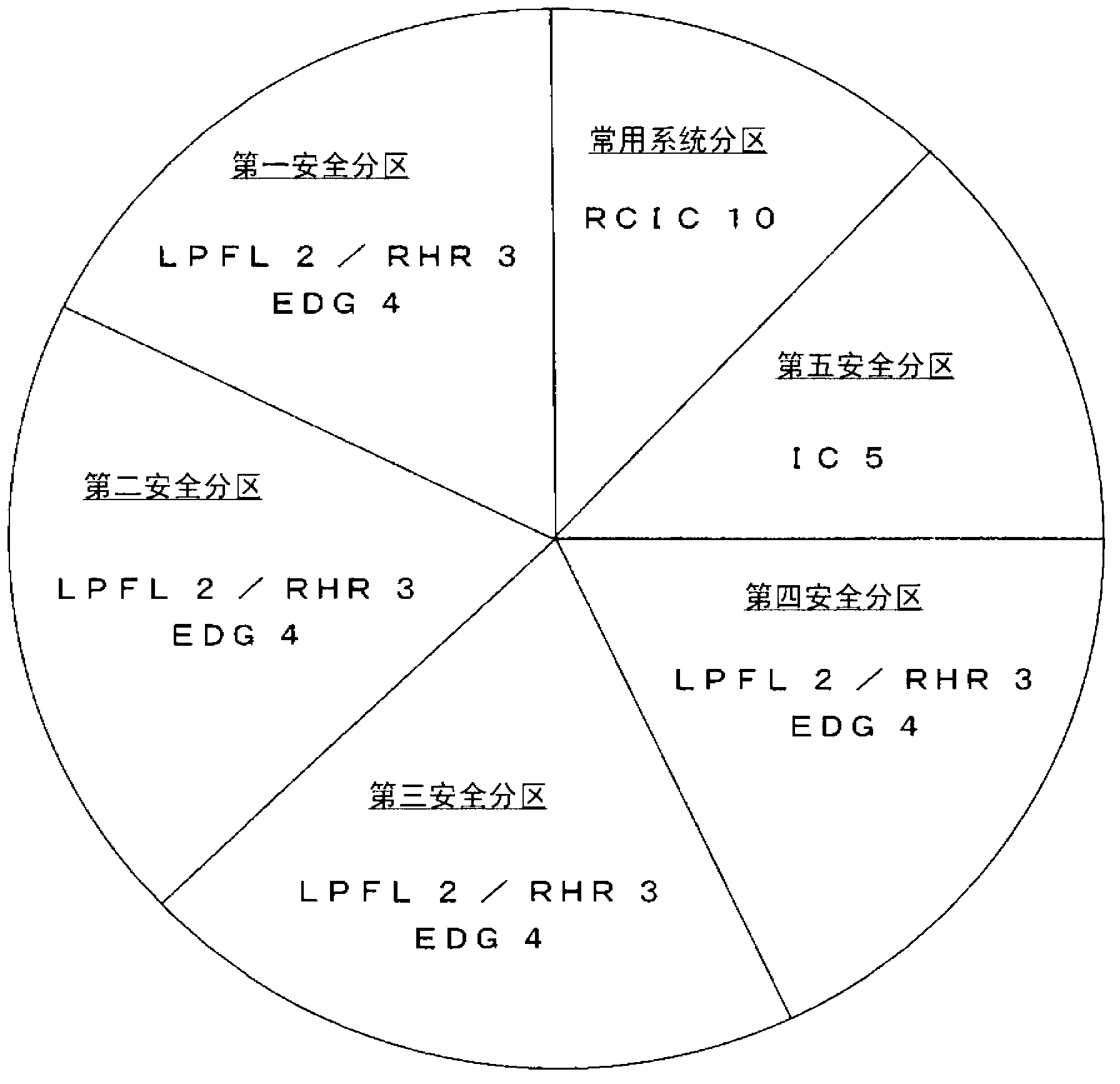
[0072] Secondly, image 3 It is a diagram showing the configuration of a core emergency cooling system according to a third embodiment of the present invention. In this embodiment, a turbine-driven Reactor Isolation Cooling System (RCIC) 10 as an auxiliary water supply system is installed in the common system partition. The reactor isolation cooling system 10 works with the main steam of the reactor as the power source, so the standby diesel generator 4 is not needed during operation. In addition, since cooling by the reactor auxiliary equipment cooling system is not required, it can be separately installed in the above-mentioned common system partition.
[0073] In the present embodiment, since the reactor isolation cooling system 10 is present, even if the overflow safety valve is stuck, the water level of the reactor can be safely maintained. Moreover, even if a small fracture cooling material loss accident occurs, the reactor will not be decompressed, and the reactor wat...
PUM
 Abstract
Description
Claims
Application Information
 - R&D
- Intellectual Property
- Life Sciences
- Materials
- Tech Scout
- Unparalleled Data Quality
- Higher Quality Content
- 60% Fewer Hallucinations
Browse by: Latest US Patents, China's latest patents, Technical Efficacy Thesaurus, Application Domain, Technology Topic, Popular Technical Reports.
© 2025 PatSnap. All rights reserved.Legal|Privacy policy|Modern Slavery Act Transparency Statement|Sitemap|About US| Contact US: help@patsnap.com