
Automatic patching machine

An automatic placement machine and frame technology, applied in the direction of electrical components, electrical components, etc., can solve the limitation of component manufacturers' shipments and cost control, production efficiency cannot meet large-scale integrated production, procurement costs and High maintenance costs and other issues, to achieve the effect of reducing equipment procurement costs, occupying a small space, and simple structure

Active Publication Date: 2013-07-24
深圳市东旭发自动化有限公司
View PDF5 Cites 41 Cited by
  • Summary
  • Abstract
  • Description
  • Claims
  • Application Information

AI Technical Summary

Problems solved by technology

The efficiency of manual lamination is low, and the labor cost is high, which limits the shipment volume and cost control of component manufacturers
The purchase cost and maintenance cost of the existing placement machine are high, and the defect rate of bonding is high, and the existing placement machine has only one operating element, which makes its production efficiency still unable to meet the requirements of large-scale integrated production. Require

Method used


Image

  • Automatic patching machine
  • Automatic patching machine
  • Automatic patching machine

Examples


Embodiment Construction

[0031] Below, in conjunction with accompanying drawing and specific embodiment, the present invention is described further:

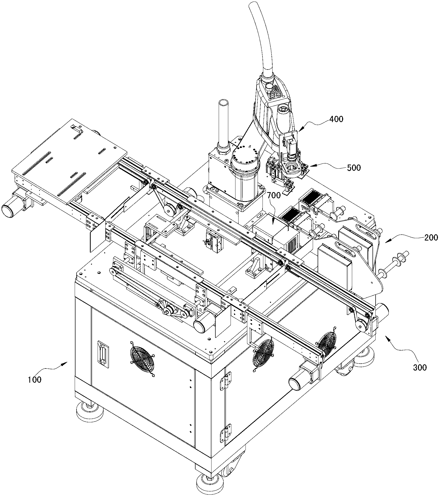
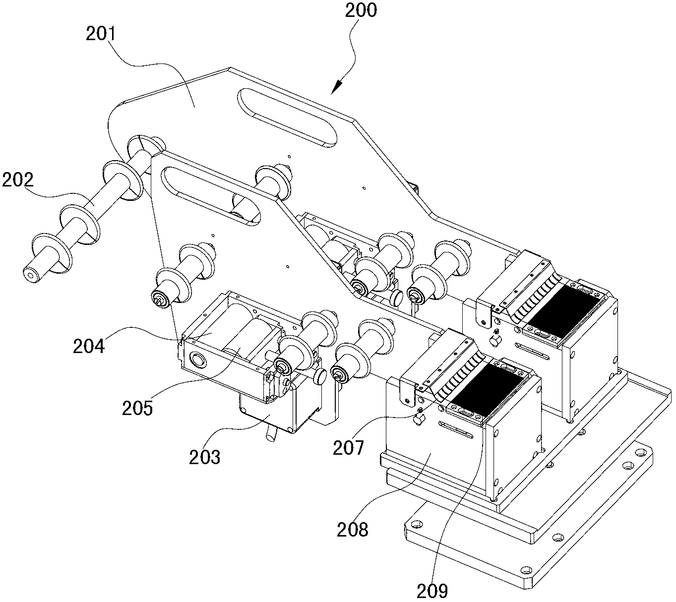
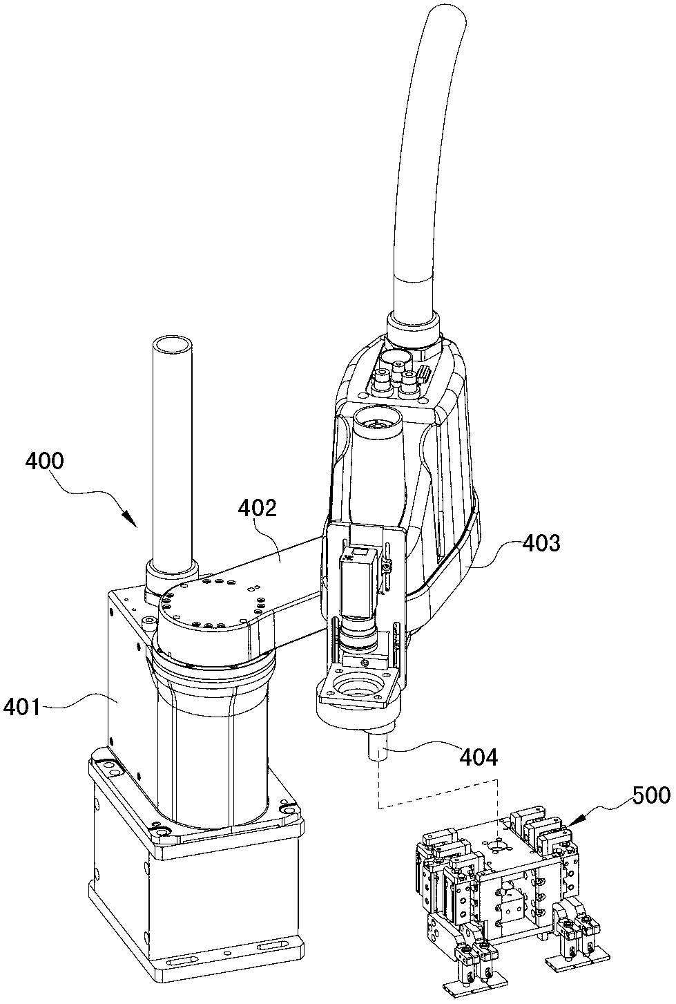
[0032] see figure 1 , 2 , 3, 4, 5, the automatic placement machine of the present invention includes a frame 100, and a conveying assembly 300, a feeding assembly 200, and a manipulator 400 installed on the table top of the rack 100; the conveying assembly 300 is used to convey the object to be pasted, It includes a loading buffer station 310, a bonding station 320, and a discharging buffer station 330 in sequence along the conveying direction. The bonding station 320 is used for placement operation, and the discharge buffer station 330 is used for unloading. The loading buffer station 310, lamination station 320, and discharge buffer station 330 are all independent delivery units. Conveyor assembly 300 comprises the transmission frame that is installed on the frame 100, is respectively provided with a first transmission belt 311 extending along the l...


PUM


Abstract

The invention relates to an automatic patching machine, which comprises a machine frame, a conveying assembly, a feeding assembly and a mechanical hand, wherein the conveying assembly is arranged on the machine frame, is used for conveying a patched object and sequentially comprises a material supply buffer station, a patching station and a material discharging buffer station in the conveying direction of the conveying assembly, and the material supply buffer station, the patching station and the material discharging buffer station respectively and independently form a conveying unit; the feeding assembly is arranged on the machine frame and is used for feeding patching objects; and the mechanical hand is arranged on the machine frame, the free end of the mechanical hand is provided with a gripping assembly used for gripping the patching object at the tail end of the feeding assembly, and the mechanical hand is used for driving the gripping assembly to move between the material discharging end of the feeding assembly and the patching station of the conveying assembly. Compared with the prior art, the automatic patching machine can simultaneously grip a plurality of patching objects for carrying out gradual patching, the manual operation is replaced, and the patching efficiency is greatly improved; because the mechanical hand is adopted as an active moving element, the maintenance is relatively simpler; the positioning is realized through a CCD (charge coupled device), the patching precision is improved, and the defective rate is reduced; and in addition, the automatic patching machine has the advantages that the structure is simple, the assembly is simple, the occupied space of the whole machine is relatively smaller, and the purchasing cost of equipment of manufacturers is greatly reduced.

Description

[0001] technical field [0002] The invention relates to a reinforcing device for electronic components, in particular to an automatic placement machine. [0003] Background technique [0004] In the process of processing electronic components, because of the low strength of a large number of electronic components, it is necessary to attach reinforcing sheets to the weaker parts to make the strength of electronic components meet the requirements of use. According to the nature of the product, the patch work is usually done manually or by machine. The efficiency of manual lamination is low, and the labor cost is high, which limits the shipment volume and cost control of component manufacturers. The purchase cost and maintenance cost of the existing placement machine are high, and the defect rate of bonding is high, and the existing placement machine has only one operating element, which makes its production efficiency still unable to meet the requirements of large-scale int...

Claims


Application Information

Patent Timeline
IPC IPC(8): H05K13/04
Inventor 黄超
Owner 深圳市东旭发自动化有限公司
Learn More