
Large-current closed inflatable spark interval

A spark gap and high current technology, applied in spark gaps, electrical components, circuits, etc., can solve the problems of reducing the insulation level between the upper and lower electrodes, the insulating screw is easy to form impurity layers, and the connection cannot be guaranteed to be compact and reliable, so as to reduce the switch Structural size, ensure the insulation ability along the surface, ensure the effect of contact area and tightness

Active Publication Date: 2014-07-23
武汉华中华昌能源电气科技有限公司
View PDF9 Cites 0 Cited by
  • Summary
  • Abstract
  • Description
  • Claims
  • Application Information

AI Technical Summary

Problems solved by technology

However, they all inevitably have the following serious disadvantages: 1) In order to ensure the airtightness of the switch, insulating screws are often used for reinforcement, and the aging of the insulating screws will lead to a decrease in airtightness. The former increases the difficulty of assembly, and the latter The latter increases the difficulty of maintenance, and at the same time, it is easy to form an impurity layer on the insulating screw, which reduces the insulation level between the upper and lower electrodes; 2) In order to reduce the ablation between the electrode and the electrode support and improve the flow capacity, it is necessary to ensure that the connection between the two is tight. The common methods (thermal expansion and contraction method or pressure ring method) are more complicated to realize, and cannot guarantee the compactness and reliability of the connection, and the life of the switch will be greatly reduced after long-term use; 3) The gap distance between the electrodes is fixed, resulting in a small range of use. To change the electrode gap distance, the structural size of the entire switch needs to be changed, which is difficult to adapt to changing scientific research needs

Method used


Image

  • Large-current closed inflatable spark interval

Examples


Embodiment Construction

[0022] The specific embodiments of the present invention will be further described below in conjunction with the accompanying drawings. It should be noted here that the descriptions of these embodiments are used to help understand the present invention, but are not intended to limit the present invention. In addition, the technical features involved in the various embodiments of the present invention described below can be combined with each other as long as they do not constitute a conflict with each other.

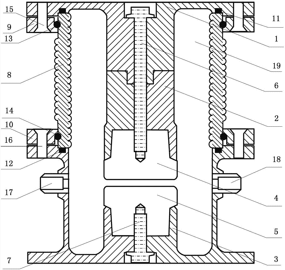
[0023] Such as figure 1 As shown, the high-current closed gas spark gap gas switch provided by the present invention adopts a coaxial structure in appearance, and it specifically includes a metal cover plate 1, an upper electrode support 2, a lower electrode support 3, an upper electrode 4, and a lower electrode 5 , Upper screw rod 6, lower screw rod 7, insulating sleeve 8, upper metal plate 9, lower metal plate 10, upper sealing washer 11, lower sealing washer 12, uppe...


PUM


Abstract

The invention discloses a large-current closed inflatable spark interval so as to achieve high reliability, high gas tightness and the like of a gas switch and enlarge application range of the gas switch. The spark interval comprises a metal cover board, an upper electrode supporting base, a lower electrode supporting base, an upper electrode, a lower electrode, an insulating sleeve, an upper metal disc, a lower metal disc, an upper metal hoop and a lower metal hoop, wherein the metal cover board is arranged coaxially. The insulating sleeve is designed through wavy skirt edges so as to increase the edge surface distance between the metal cover board and the lower electrode supporting base. The upper electrode supporting base and the metal cover board are manufactured separately, and the mechanical connection of the upper electrode supporting base and the metal cover board can be achieved through an upper screw. The two metal discs which can move freely are led in so as to achieve the mechanical connection among the metal cover board, the lower electrode supporting base and the insulating sleeve. The upper screw is in tight connection with the upper electrode through a thread structure, a lower screw is in tight connection with the lower electrode through a thread structure, so that replacement is more convenient. A circular truncated cone is designed to ensure the contact area and tightness between each electrode and each electrode supporting base, increase the reliability of the gas switch, reduce the ablation volume of contact portions, and prolong the service life of the switch.

Description

technical field [0001] The invention belongs to the gas spark switch technology, in particular to a high-current closed gas-filled spark gap, that is, a spark switch. Background technique [0002] Pulse power technology has extremely important applications in national defense scientific research and high-tech fields, and now it has been more used in industrial and civilian fields, and has extremely broad development and application prospects. The basic principle of pulse power technology is to quickly release the high-density energy stored for a long time to the load through compression conversion. Pulse power technology often involves the application of high amplitude voltage, high current and steep pulse gas discharge. [0003] The switch of high current and high coulomb quantity transfer plays an extremely important role in the pulse power system, such as in inertial confinement fusion, electromagnetic launch and other devices. In the application of these devices, it is...

Claims


Application Information

Patent Timeline
Patent Type & Authority Patents(China)
IPC IPC(8): H01T14/00
Inventor 李黎俞斌潘垣张钦林福昌鲍超斌
Owner 武汉华中华昌能源电气科技有限公司
Learn More