
A double-terminal fault location method independent of transition resistance and load current

A technology of load current and transition resistance, which is applied in the field of fault location at both ends of the line, can solve problems such as poor practicability, complex exponential calculation, and difficulty in implementing microcomputer codes, and achieves the effect of high speed and small amount of calculation

Active Publication Date: 2015-08-05
STATE GRID FUJIAN ELECTRIC POWER CO LTD +3
View PDF6 Cites 0 Cited by
  • Summary
  • Abstract
  • Description
  • Claims
  • Application Information

AI Technical Summary

Problems solved by technology

This method uses the phase-to-phase fault electrical quantity to calculate the fault location. Since the phase-to-phase fault electrical quantity only exists under the phase-to-phase fault condition, this method is only suitable for phase-to-phase fault distance measurement, and this method needs to involve complex exponential calculations, and the computer code is implemented Difficult, poor practicality
[0005] The invention patent with the application number of 200710178357.9 "the method of combining phasor and zero-sequence quantity to realize the distance measurement method at both ends of transmission lines" uses zero-sequence electrical quantities. It is suitable for double-terminal distance measurement of grounding faults on transmission lines, but not applicable to other types of faults on transmission lines, and this method needs to involve complex exponential calculations, which is difficult to implement with computer codes and has poor practicability

Method used


Image

  • A double-terminal fault location method independent of transition resistance and load current
  • A double-terminal fault location method independent of transition resistance and load current
  • A double-terminal fault location method independent of transition resistance and load current

Examples


Embodiment Construction

[0023] The technical solution of the present invention will be further described in detail according to the accompanying drawings.

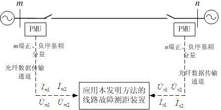
[0024] figure 1 It is a schematic diagram of a transmission line fault applying the method of the present invention. figure 1 Positive and Negative Sequence Voltages of Substation on Side m of Medium Transmission Line Positive and negative sequence current and the positive and negative sequence voltages of the n-side substation of the transmission line Positive and negative sequence current It is measured by the synchrophasor measurement unit (phase measurement unit, PMU) installed on the m-side and n-side substations of the transmission line respectively. The measurement data is transmitted to the transmission line fault location device through optical fiber communication, and the transmission line fault location device The method of the invention is used to complete the fault distance measurement function for the fault line.

[0025] C...


PUM


Abstract

The invention belongs to the technical field of power system fault positioning and discloses a fault location method for two ends of a line irrelevant with transition resistance and load current. The fault location method comprises that a fault location device detects positive and negative sequence voltage and positive and negative sequence current of the two ends of the power transmission line, performs distributed current compensation to the positive and negative sequence voltage and the positive and negative sequence current of the two ends of the power transmission line and then utilizes the positive and negative sequence voltage and positive and compensated negative sequence current of the two ends of the power transmission line to directly calculate fault positions. The fault location method is applied to quick fault positioning of the two ends of the power transmission line, influence of distributed capacitance to the accuracy of positioning results is eliminated, the fault positions are not required to be calculated by means of a search algorithm, operation quantity is low, and the fault positioning speed is high. The fault location method utilizes double-end sequence components to achieve the fault positioning of the two ends of the power transmission line, is suitable for the fault positioning of the whole fault process of any fault of the power transmission line and has universal applicability.

Description

technical field [0001] The invention relates to the technical field of power system fault distance measurement, in particular to a double-terminal fault distance measurement method of a line that is independent of transition resistance and load current. Background technique [0002] Fault location methods can be divided into double-ended location methods and single-ended location methods according to the data sources used. Due to the influence of transition resistance, the ranging accuracy of the single-ended ranging method has serious deviations, and more than 90% of high-resistance ground faults fail to perform single-ended ranging. The field practical effect is poor, and it cannot adapt to the increasingly complex power grid operation mode. Due to the large amount of fault information available, the double-ended fault location method of transmission lines is more accurate than the single-ended fault location method, and has been widely used in the field. [0003] The inv...

Claims


Application Information

Patent Timeline
Patent Type & Authority Patents(China)
IPC IPC(8): G01R31/08
Inventor 林富洪曾惠敏
Owner STATE GRID FUJIAN ELECTRIC POWER CO LTD
Learn More