Support frame with auxiliary supporting points

A support frame and support point technology, which is applied in the field of support frames, can solve problems such as unstable support of the support frame and rollover of the supported object, and achieve the effects of not being easy to roll over, high stability, and good technical effects

Inactive Publication Date: 2013-07-17
KUN SHAN POWER STENCIL
View PDF12 Cites 0 Cited by
  • Summary
  • Abstract
  • Description
  • Claims
  • Application Information

AI Technical Summary

Problems solved by technology

[0009] The technical problem to be solved by the present invention is that the supporting frame in the prior art is unstable, and the supported object is prone to rollover. It provides a new supporting frame with auxiliary support points. advantages of stability

Method used


Image

  • Support frame with auxiliary supporting points
  • Support frame with auxiliary supporting points
  • Support frame with auxiliary supporting points

Examples


Embodiment 1

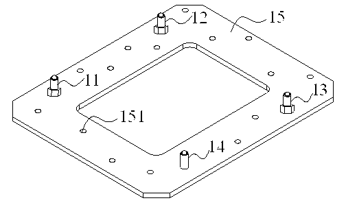
[0031] This embodiment provides a support frame with auxiliary support points, such as figure 1 As shown, it includes three hard-point support columns 11, 12, 13, a soft-point support column 14 and an abutment 15 for fixing the support column, and the three hard-point support columns 11, 12, 13 are distributed in different positions of the abutment Above, the points at its position form a right triangle, the soft point support column 14 is in the outer area of ​​the triangle, and the positions of the four support columns form a rectangular structure.

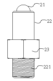
[0032] The three hard point support columns 11, 12, 13 are made of hard wear-resistant stainless steel, and their structure is as follows: figure 2 As shown, it consists of a support end spherical structure 21 embedded in one end of the support column column bar body 22, the other end of the support column column bar body 22 is a threaded structure 221, and the nut 23 is fixed on the support column column bar body 22 by thread...

Embodiment 2

[0037] The structure of the hard point support column in this embodiment is the same as that in Embodiment 1, and other threaded holes on the abutment are used in the arrangement, such as Figure 4 As shown, the corresponding soft point support column 41 is fixed at a different position compared with Embodiment 1. In addition, the structure of the soft point support column 41 is made of a rubber material with certain elasticity. Its structural diagram is as follows Figure 5 shown.

Embodiment 3

[0039] This embodiment provides a support frame with auxiliary support points, the structure of which is the same as that of Embodiment 1, and three support columns are distributed near the periphery of the abutment; and the materials are all made of hard wear-resistant stainless steel. The support column is fixed on the hard abutment by welding, and the hard abutment is made of light aluminum material; the positions of the three support columns form the three vertices of a triangle, and the triangle formed is a right triangle, and the support column The line connecting the points at the positions of 11 and support column 12 is L1, the line connecting the points at the positions of support column 12 and support column 13 is L2, and there is L1=L2, that is, the formed triangle is an isosceles right triangle.

[0040]


PUM


Abstract

The invention relates to a support frame with auxiliary supporting points. According to the support frame with the auxiliary supporting points, the problems that the surface of a surface contact type operation desk can not be guaranteed to be flat enough, and a supported object is likely to turn on one side in the prior art are solved. The support frame with the auxiliary supporting points comprises three hard-spot shores, a soft-spot shore and a base station used for fixing the shores, wherein points of positions, at which the three hard-spot shores are distributed, of the base station form a triangle, and the soft-spot shore is positioned on the external area of the triangle. According to the technical scheme that the supporting position of the shore is in a curved surface structure or a taper-shaped structure, the problems are better solved, and the support frame with the auxiliary supporting points can be used for the industrial production of the support frame and a support platform for the precise operation.

Description

technical field [0001] The invention relates to a support frame with auxiliary support points. Background technique [0002] With the development of society, various industries have higher and higher requirements for the placement environment and bearing platform of the hardware facilities involved in the industry, especially for the placement of some precision instruments. For example, in the operation table involving the work of optical components, it is often required that the supporting platform has sufficient stability. [0003] Chinese patent CN101738127A discloses a heat-insulating support device, which includes a cold platform with multiple mounting holes and a support rod for supporting the cold platform, and the support rod includes an upper support rod and a lower support rod. Cooperate with the mounting holes in a point contact or line contact manner respectively, but the support frame of the invention has four support columns. [0004] Chinese patent CN2574502...

Claims


Application Information

Patent Timeline
Patent Type & Authority Applications(China)
IPC IPC(8): F16M11/00
Inventor 魏志凌高小平程晔
Owner KUN SHAN POWER STENCIL
Why Eureka
Try Eureka