
Float polishing head

A polishing head and transmission shaft technology, applied in the field of floating polishing head, can solve problems affecting the surface quality of workpieces, etc.

Inactive Publication Date: 2015-02-18
DALIAN UNIV OF TECH
View PDF7 Cites 4 Cited by
  • Summary
  • Abstract
  • Description
  • Claims
  • Application Information

AI Technical Summary

Problems solved by technology

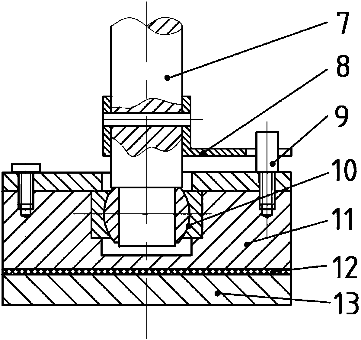
[0004] Aiming at the technical defect of the existing floating polishing head that the instantaneous center is too high, which will cause overturning moment and affect the surface quality of the workpiece, the present invention proposes a new type of floating polishing head with low instantaneous center. The spherical rolling bearing structure replaces the ordinary joint bearing structure

Method used


Image

  • Float polishing head
  • Float polishing head
  • Float polishing head

Examples


Embodiment Construction

[0016] The specific embodiment of the present invention is described in detail in conjunction with technical scheme and accompanying drawing: For image 3 The shown low instantaneous center floating polishing head is composed of transmission shaft 19, upper cover 20, lower cover 25, upper ball 15, lower ball 16, upper cage 21, lower cage 17, pull rod 24, rubber bellows 23, The upper set screw 14, the lower set screw 18 and the clamping part 26 etc. are composed. The lower part of the drive shaft 19 is a spherical structure in contact with the lower ball 16, and its upper part is used to be connected to the end of the machine tool spindle. The upper cover 20 is screwed with the middle threaded locking part of the transmission shaft 19. The bottom surface of the upper cover 20 is a concave spherical surface, and there are two screw holes on the side, and the position is locked by the upper set screw 14. The lower cover 25 has two spherical structures inside and outside. The con...


PUM


Abstract

The invention relates to a float polishing head with a double spherical rolling bearing structure replacing a common joint bearing structure. The float polishing head comprises a transmission shaft, an upper cover, a lower cover, an upper ball, a lower ball, an upper retainer, a lower retainer, pull rods, a rubber bellows, fastening screws, a clamping portion and the like, sphere centers are overlapped to form a swinging instant center of a joint after four spherical parts are assembled, the swinging instant center can be designed on a contact plane of a workpiece and a polishing pad, the moment arm of grinding resistance to the swinging instant center is zero, accordingly, overturning moment is thoroughly eliminated, and uniform contact pressure is applied to the machined surface of the workpiece. The polishing head transmits driving torque through the two pull rods, a swinging joint structure is protected from corrosion by the rubber bellows, and workpiece plane machining precision can be structurally improved.

Description

technical field [0001] The invention relates to a polishing machine component, in particular to a floating polishing head capable of overcoming the overturning moment during polishing, which is beneficial to improving the precision and surface quality of workpieces. Background technique [0002] Chemical mechanical polishing is a method commonly used in precision and ultra-precision machining to improve the surface quality and planarization of the workpiece surface. The horizontal polishing disc carrying the polishing pad rotates, and the workpiece is fixed on the back film of the clamping part of the polishing head. The workpiece is pressed against the rotating polishing pad by a steady vertical pressure, and at the same time it rotates, and the polishing liquid delivery device will The polishing liquid containing abrasive grains is transported to the polishing pad, and the components in the polishing liquid chemically react with the workpiece, and the reaction products for...

Claims


Application Information

Patent Timeline
Patent Type & Authority Patents(China)
IPC IPC(8): B24B37/11B24B37/07
Inventor 戴恒震张宝民贾晟辉洪宁远金洙吉
Owner DALIAN UNIV OF TECH
Learn More