
Pulley mechanism with tensioning mechanism

A pulley mechanism and tensioning mechanism technology, applied in belts/chains/gears, mechanical equipment, transmissions, etc., can solve problems such as inconsistent force, inability to absorb changes in synchronous belt tension, and inconsistent dynamic characteristics of arms

Active Publication Date: 2015-11-18
SHENYANG SIASUN ROBOT & AUTOMATION
View PDF5 Cites 0 Cited by
  • Summary
  • Abstract
  • Description
  • Claims
  • Application Information

AI Technical Summary

Problems solved by technology

However, when the unilateral tensioning method is used, the timing belt tension on the tensioning side is inconsistent with the force on the non-tensioning side timing belt, which will lead to inconsistent dynamic characteristics of the robot arm during extension and retraction
When using double inner tensioning, since the position of the tensioning wheel is fixed, it cannot absorb the change in timing belt tension caused by structural processing errors. In addition, although the double inner tensioning method solves the problem of inconsistent force, it does not But it is based on the premise of sacrificing the wrap angle of the synchronous belt
In addition, the idler gear with double inner tension needs to process teeth, and this tooth increases the processing cost and increases the difficulty of the design of the tensioner
In addition, the size of the shell will be increased from the double inner tension method

Method used


Image

  • Pulley mechanism with tensioning mechanism

Examples


Embodiment Construction

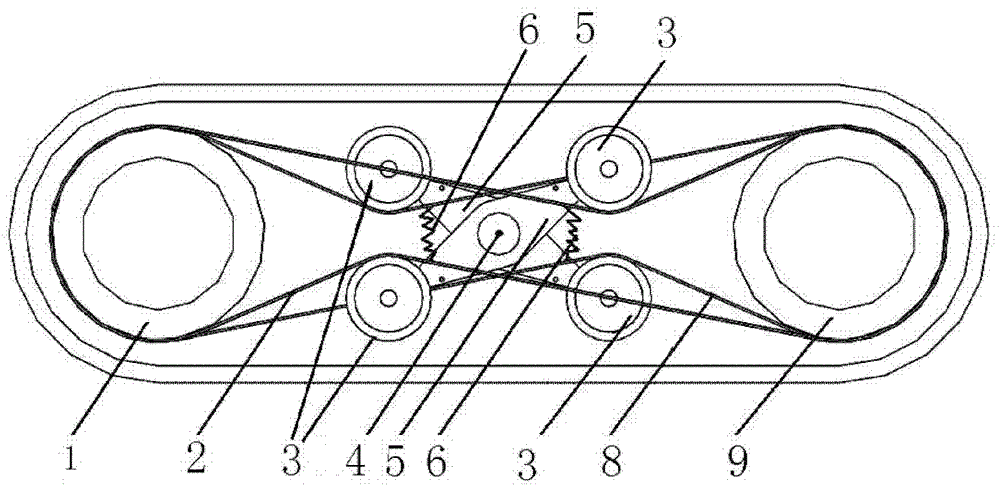
[0017] Please refer to figure 1 , In one embodiment of the present invention, a pulley mechanism includes a driving pulley 1, a driven pulley 9, an upper synchronous belt 2, a lower synchronous belt 8, and a tensioning mechanism. The upper side synchronous belt 2 and the lower side synchronous belt 8 are sleeved on the driving wheel 1 and the driven wheel 9, through the upper side synchronous belt 2 and the lower side synchronous belt 8, the driving wheel 1 can drive the driven wheel 9 rotate synchronously.

[0018] The tensioning mechanism includes four tensioning wheels 3 , two swing rods 5 , a rotating shaft 4 and two adjustment springs 6 . Two tensioning pulleys 3 are connected on the two opposite ends of a fork 5 through shafts (figure not marked), and can rotate freely around the shaft. Each swing link 5 is mounted on the rotating shaft 4 and can freely rotate around the rotating shaft 4 . One end of each adjustment spring 6 is connected with a fork 5, and the other e...


PUM


Abstract

A belt wheel mechanism comprises a driving wheel, a driven wheel and a synchronous belt sleeved on both the driving wheel and the driven wheel, as well as the tensioning mechanism, wherein the driving wheel rotates to drive the driven wheel to rotate through the synchronous belt; the tensioning mechanism comprises a rocking beam, two tensioning wheels, a fixed rotating shaft and a regulating spring, and the rocking beam is rotationally fixed on the rotating shaft; the two tensioning wheels are rotationally fixed at two opposite ends of the rocking beam to squeeze the synchronous belt; and one end of the regulating spring is fixed on the rocking beam, and the other end is fixed on a structure not in follow-up with the rocking beam.

Description

technical field [0001] The invention relates to a pulley mechanism, in particular to a pulley mechanism with a tensioning mechanism. Background technique [0002] A clean robot is an industrial robot used in a clean environment. With the continuous improvement of the production technology level, the requirements for the production environment are becoming increasingly stringent. Many modern industrial products are required to be produced in a clean environment. Clean robots are key equipment for production in a clean environment. There are two main ways of tensioning the timing belt of the existing cleaning robot arm: one is unilateral tensioning, that is, tensioning from the outer side of the timing belt with a driven wheel; the other is double inner tensioning, that is, using two The pulleys are tensioned simultaneously on both sides of the timing belt. However, when the unilateral tensioning method is used, the tension of the timing belt on the tensioning side is incons...

Claims


Application Information

Patent Timeline
Patent Type & Authority Patents(China)
IPC IPC(8): F16H7/08
Inventor 温燕修孙义田张一博徐方李学威边弘晔郑鋆王凤利
Owner SHENYANG SIASUN ROBOT & AUTOMATION
Learn More