Fuel injector for free piston type engine

A piston engine, fuel injection technology, applied in free piston engine, engine element, machine/engine, etc., to achieve low cost effect

Inactive Publication Date: 2013-07-10
ANHUI ZHONGDING POWER
View PDF7 Cites 2 Cited by
  • Summary
  • Abstract
  • Description
  • Claims
  • Application Information

AI Technical Summary

Problems solved by technology

[0006] However, there is a question of how to design fuel injection in such an arrangement to minimize cost and minimize engine construction while maintaining fuel efficiency

Method used


Image

  • Fuel injector for free piston type engine
  • Fuel injector for free piston type engine
  • Fuel injector for free piston type engine

Examples


Embodiment Construction

[0034] The present invention will be further described below in conjunction with the accompanying drawings and specific embodiments, but not as a limitation of the present invention.

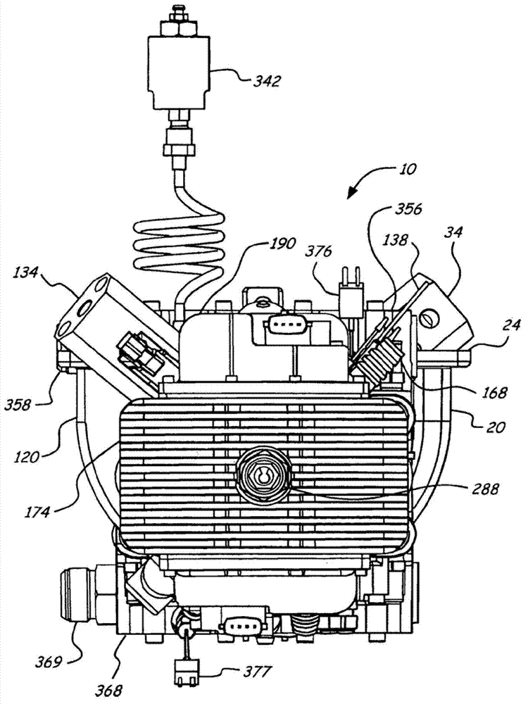
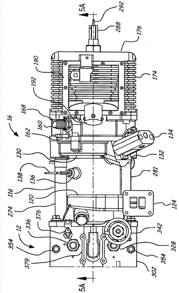
[0035] Such as Figure 1-16 A fuel injector for a free-piston engine of the present invention is shown, comprising a free-piston engine 10 composed of a hydraulic pump body assembly 12, a first cylinder assembly 14, and a second cylinder assembly 16. The free-piston engine 10 not only Store the energy in the form of pressurized fluid produced by the engine, and can start with part of the pressurized fluid, which can sometimes help to control the operation of the engine and maintain the balance of the engine. The first cylinder assembly 14 is connected to one side of the hydraulic pump body assembly 12, the second The second cylinder assembly 16 is connected to the other side of the hydraulic pump body assembly 12; the first cylinder assembly 14 comprises a first engine cylinder, and the extensio...


PUM


Abstract

The invention discloses a fuel injector for a free piston type engine. The fuel injector comprises a hydraulic pump body assembly, a first air cylinder assembly and a second air cylinder assembly, wherein a first air inlet, a first exhaust opening and a first fuel injection port close to the first air inlet are formed in the extending surface on the cylinder wall of the first air cylinder assembly; a first spray nozzle of the first fuel injector is positioned in the first fuel injection port; a second air inlet, a second exhaust opening and a second fuel injection port close to the second air inlet are formed in the extending surface on the cylinder wall of the second air cylinder assembly; and a second spray nozzle of the second fuel injector is positioned in the second fuel injection port. The fuel injector disclosed by the invention has the benefits that a fuel injector with lower use cost can be used; the fuel is prevented from being contacted with the air cylinder wall; more-uniform mixed oil gas is ensured; the fuel injector is positioned nearby close to the air inlet, so that the fuel can be directly injected to the air cylinder; and meanwhile, the fuel injector can be allowed to leave from the burning range. Therefore, the fuel injector is prevented from being exposed in a severe burning environment.

Description

technical field [0001] The invention relates to a free-piston engine, in particular to a fuel injector for a free-piston engine. Background technique [0002] Typically, internal combustion engines operate by mechanically constraining the movement of pistons. For example, a conventional automotive internal combustion engine consists of a crankshaft and connecting rod assembly, the mechanisms that determine how the pistons in the corresponding cylinders move. Such an engine is suitable because the position of each piston is determined at any given point in the engine cycle, which simplifies timing and engine operation. Although the efficiency of traditional engines has been greatly improved in recent years, their efficiency is still limited due to the limitations of the engine structure. In particular, the specific power of the engine is limited because the mechanically limited movement of the piston creates a fixed compression ratio. In addition, all the moving parts that...

Claims


Application Information

Patent Timeline
IPC IPC(8): F02B71/00F02B75/28F02M61/14
Inventor 李传友左朝凤夏迎松陈新张永刚
Owner ANHUI ZHONGDING POWER
Why Eureka
Try Eureka